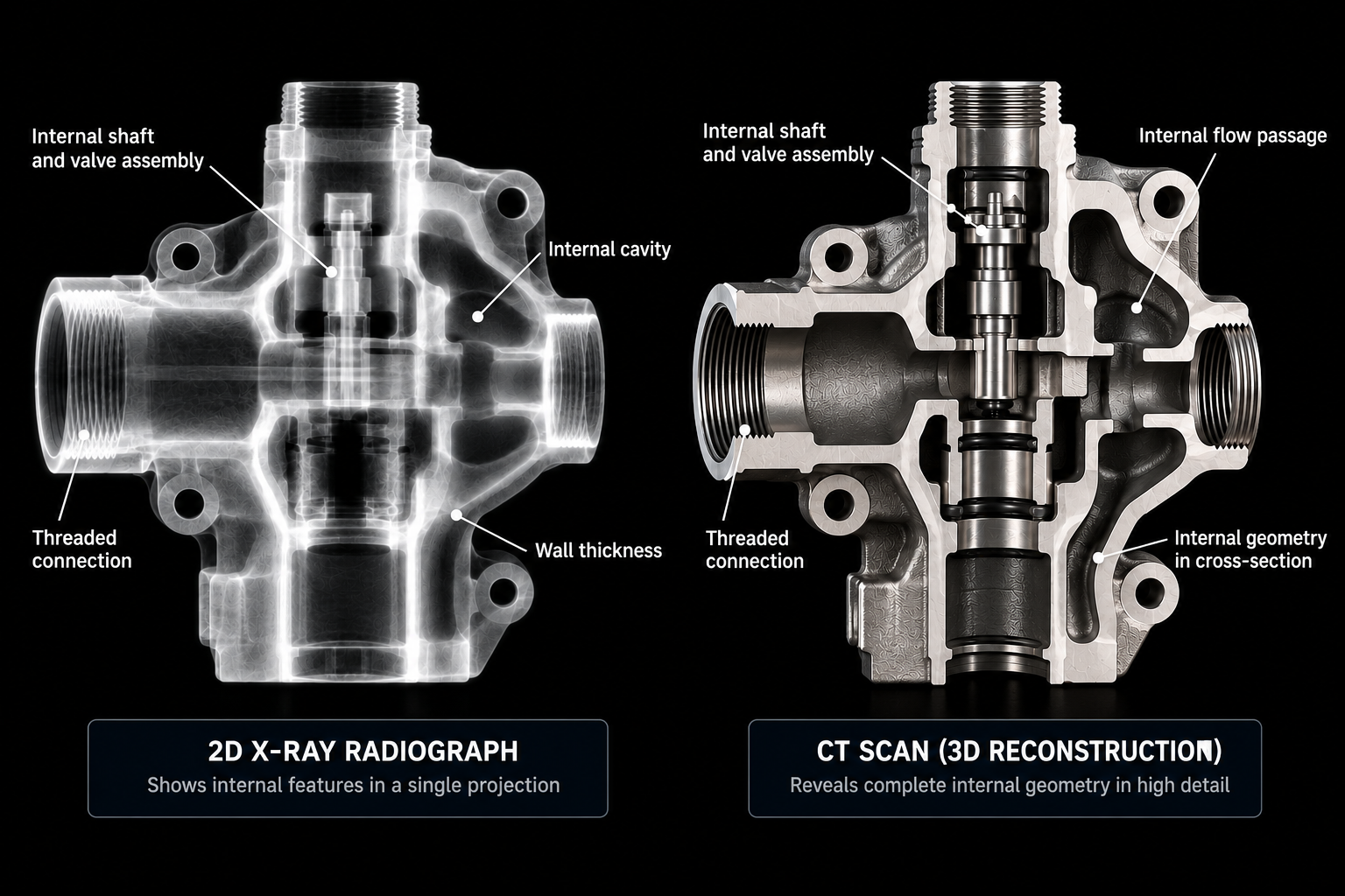
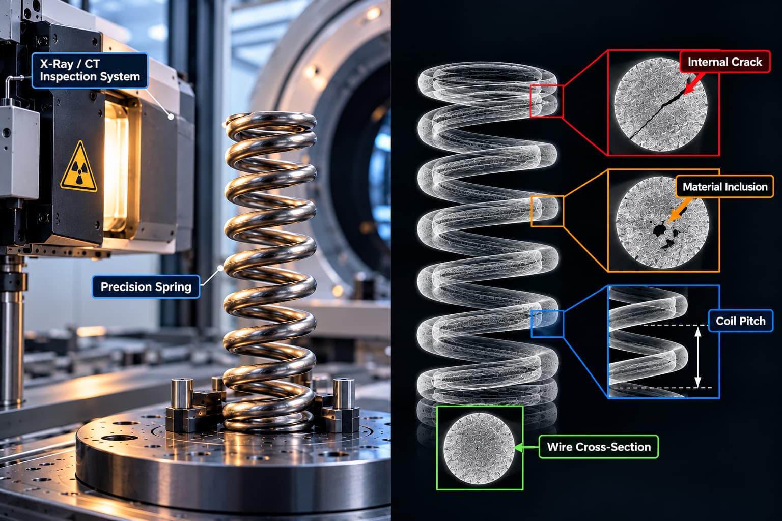
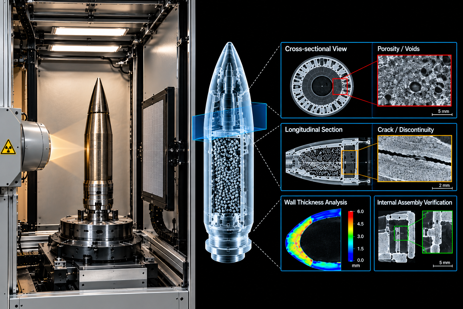
A hydraulic manifold can pass a pressure test and still fail in service weeks later, once a burr loosened by flow erosion finally breaks free and lodges in a downstream valve seat. Pressure testing confirms that a system holds its rated pressure; it does not show where inside a block of cross-drilled passages a defect actually sits. CT inspection addresses this gap directly, verifying internal flow paths, valve-seat geometry, and manifold integrity in a single nondestructive scan rather than inferring internal condition from an external pressure reading.
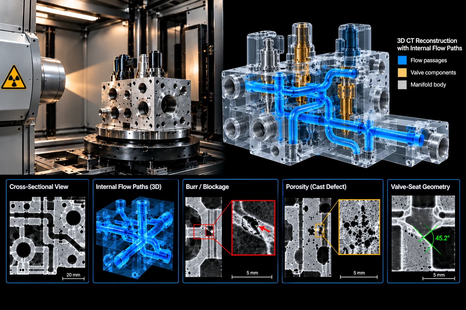
CT reconstruction of a hydraulic manifold showing internal flow paths, a cross-drilled passage burr, cast porosity, and valve-seat angle, each verified directly from a single volumetric scan.
Why Flow Paths Resist Conventional Inspection
Hydraulic manifolds are typically machined or cast with multiple cross-drilled passages intersecting at odd angles, connecting ports that were never designed to be inspected from any single external vantage point. Pressure testing confirms the system holds pressure without revealing where, specifically, a restriction, leak path, or internal defect is located. Borescope inspection reaches straight bores but cannot follow a passage around an internal intersection. CT resolves this limitation by reconstructing the complete internal channel network in three dimensions, independent of how the passages intersect or where they terminate.
Mapping Internal Channels and Passage Geometry
The first step in CT inspection of a hydraulic valve or manifold is reconstructing the full internal channel network from the scan data, producing a 3D model of every connected passage as it actually exists in the part, not as it was originally drawn. This reconstructed geometry is then compared directly against the manifold’s nominal CAD design, surfacing dimensional deviation in bore diameter, passage angle, or intersection geometry that a pressure or flow test would only reveal indirectly, through reduced performance rather than a located cause. This same channel-mapping approach applies directly to hydraulic components already inspected by CT, including the hydraulic fluid channels and piston bores verified in brake caliper inspection, where internal flow geometry carries comparable safety consequences.
Identifying Manufacturing Defects Along the Flow Path
Once the channel geometry is mapped, the same CT dataset is examined for defects that could compromise flow or structural integrity: burrs left behind from cross-drilling operations, blockages from incomplete deburring or trapped machining debris, and porosity or cracking in cast manifold bodies. Many hydraulic manifolds are sand-cast or die-cast before final machining, carrying the same shrinkage porosity and inclusion risk documented in CT inspection of sand-cast iron and steel parts, where a cast valve body was examined for exactly this category of internal defect. A burr positioned at a passage intersection is particularly consequential, since flow erosion can eventually dislodge it into a downstream valve seat long after the part has passed initial inspection.
Verifying Valve-Seat Geometry and Seal Interfaces
Valve-seat geometry determines whether a hydraulic valve seals correctly under pressure, and CT measures seat roundness, angle, and surface condition directly from the reconstructed volume rather than relying on a separate sealing test to infer geometric accuracy. Where a manifold incorporates rubber or elastomeric sealing elements, such as diaphragms or O-ring interfaces, the same scan extends naturally to the kind of bond and seal verification covered in X-ray inspection of rubber-to-metal bonded parts and sealing components, which specifically addresses hydraulic seals and valve diaphragms as a defect category distinct from the metal body itself.
From Prototype to Production Verification
CT inspection plays a different role depending on program stage. During prototype and design validation, full-volume scans characterize new manifold designs in detail, confirming that complex internal geometry was machined or cast as intended before tooling is finalized. In production, inspection typically shifts toward sampling or, for safety-critical hydraulic assemblies, continuous verification, an approach discussed in inline CT versus spot-check inspection, where the sampling gap inherent to spot-check methods is weighed directly against the coverage continuous CT inspection provides. XRAY-LAB supports hydraulic component manufacturers across both stages, applying the same internal-geometry verification regardless of whether the objective is design confirmation or production quality control.
Frequently Asked Questions
What hydraulic valve and manifold defects can CT detect that pressure testing cannot?
CT detects the specific location and nature of internal defects, including burrs, blockages, porosity, and cracking, while pressure testing only confirms whether the system holds its rated pressure without identifying where or why a defect exists.
How does CT visualize internal flow paths and cross-drilled passages?
CT reconstructs the complete internal channel network in three dimensions from the scan data, capturing connected passages and intersections regardless of their angle or whether they are reachable by a borescope.
Can CT detect burrs and blockages inside hydraulic channels?
CT detects burrs and blockages by identifying density differences and geometric irregularities within the reconstructed channel volume, locating obstructions precisely rather than inferring their presence from reduced flow performance.
How does CT verify valve-seat geometry and sealing surfaces?
CT measures valve-seat roundness, angle, and surface condition directly from the reconstructed volume, and extends to rubber or elastomeric sealing elements where the manifold design incorporates diaphragms or O-ring interfaces.
Is CT suitable for both prototype and production hydraulic component inspection?
CT is suitable for both; prototype inspection typically uses full-volume scans for detailed design validation, while production inspection generally shifts toward sampling or continuous inspection depending on the component’s safety criticality.