Investment casting is the process behind some of the most demanding components in aerospace and power generation, including turbine blades, vanes, and structural brackets cast from nickel and cobalt superalloys. These parts operate under combined thermal and mechanical load that leaves no margin for undetected internal defects, which is why investment casting inspection increasingly relies on X-ray CT rather than sampling-based methods alone. This blog walks through how CT-based casting defect detection NDT applies across the specific defect types and production stages that investment casting introduces.
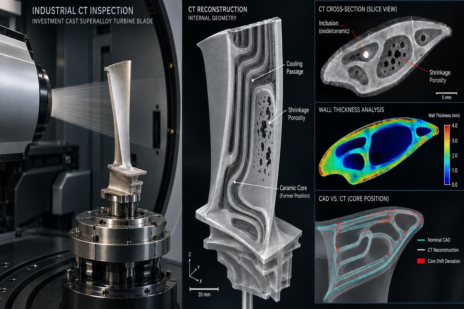
Conceptual visualization of CT inspection for investment-cast superalloy turbine blades, highlighting internal defects and dimensional verification.
Investment Casting in Aerospace and Power Generation
Superalloy investment castings are chosen specifically for their ability to hold complex, near-net-shape geometry, including the internal cooling passages found in turbine blades, while retaining strength at high operating temperature. That same geometric complexity, however, makes the casting process more prone to localized defects than simpler shapes, and it makes those defects harder to detect with conventional radiography. Superalloy casting inspection therefore depends on a method capable of resolving defect location and shape throughout a geometrically intricate volume, which is the specific advantage CT brings to this application.
Detecting Shrinkage Porosity in Superalloy Turbine Components
Shrinkage porosity forms as molten superalloy cools and contracts, concentrating in the last regions of the casting to solidify, typically near thick sections or close to gating. CT detection of shrinkage porosity in superalloy castings quantifies both the volume and spatial clustering of these voids, distinguishing genuine shrinkage from the more diffuse gas porosity that can otherwise resemble it on a flat radiograph. This same clustering analysis, using CT void mapping to correlate defect location with the casting’s gating design, gives foundries a direct path from a detected defect back to a specific process cause.
Identifying Inclusions From the Investment Casting Process
Inclusion detection in investment castings using CT separates foreign material, typically ceramic shell fragments or oxide particles introduced during pouring, from porosity based on density signature rather than shape alone, since both defect types can appear similarly rounded in a single 2D image. This distinction is significant because inclusions and porosity are frequently subject to different acceptance criteria within the same casting specification, a defect-separation principle that applies just as directly to sand-cast iron and steel parts as it does to investment cast superalloys, despite the difference in casting process.
Measuring Core Shift in Complex Cored Castings
Core shift occurs when the ceramic core defining a part’s internal geometry, such as a turbine blade’s cooling channels, moves slightly during the pour, producing wall thickness that deviates from design intent even though the external casting appears correct. Core shift measurement with industrial CT compares the as-cast internal geometry directly against nominal CAD data, catching wall thickness deviation that would otherwise go unnoticed until the part fails under thermal cycling. Verifying core position is, in effect, the same measurement problem addressed in CT inspection of turbine blade cooling channels before casting, applied here after the pour rather than before it.
Building an Internal Defect Library for Investment Cast Parts
CT for turbine blade investment castings supports more than single-part inspection; the accumulated scan data builds an internal defect library correlating defect type, size, and location with specific tooling, core sets, and process parameters over time. Foundry quality control CT programs use this library to shift from reactive defect sorting toward predictive process control, flagging tooling or core sets that produce recurring defect patterns before an entire production batch is affected. Aerospace superalloy applications benefit particularly from this approach, an extension of the same volumetric inspection principle applied in PolyCT’s work on transforming aerospace CT inspection.
XRAY-LAB's Investment Casting Inspection Expertise
XRAY-LAB inspects investment cast superalloy components across the defect types and production stages outlined above, from first-article core shift verification to production-scale shrinkage and inclusion screening. The customer outcome is consistent across these applications: fewer field failures in components that cannot be repaired or replaced without significant cost, and a documented defect record that supports both process improvement and certification requirements.
Frequently Asked Questions
Which casting defects are most reliably detected by CT?
CT reliably detects shrinkage porosity, gas porosity, inclusions, core shift, and wall thickness deviation, separating each defect type from the others based on shape, density, and spatial location within the casting.
How does CT quantify shrinkage porosity and inclusions in superalloys?
CT quantifies both defect types by volume, size distribution, and spatial clustering, using density signature to distinguish inclusions from porosity even when the two appear similar in a single projection.
Can CT measure core shift and wall thickness variation in complex castings?
CT measures core shift and wall thickness variation by comparing the as-cast internal geometry directly against nominal CAD data across the entire part volume, not only at isolated measurement points.
What resolution is needed to detect critical defects in investment cast superalloy parts?
Required resolution depends on the smallest defect size specified in the acceptance criteria for that component’s application, with turbine blade cooling passages typically demanding finer resolution than structural brackets.
How is CT used alongside other NDT methods in investment casting QA?
CT is often used alongside dye penetrant and radiographic testing, with CT providing volumetric defect location and sizing that supplements or replaces sampling-based destructive sectioning in qualification programs.