A turbine blade’s internal cooling channels are designed into the wax pattern and ceramic core long before any metal is poured. If that core geometry is wrong, undersized, misaligned, or partially collapsed, the defect is baked into the casting before the pour even happens, and it can not be corrected afterward without scrapping the part.
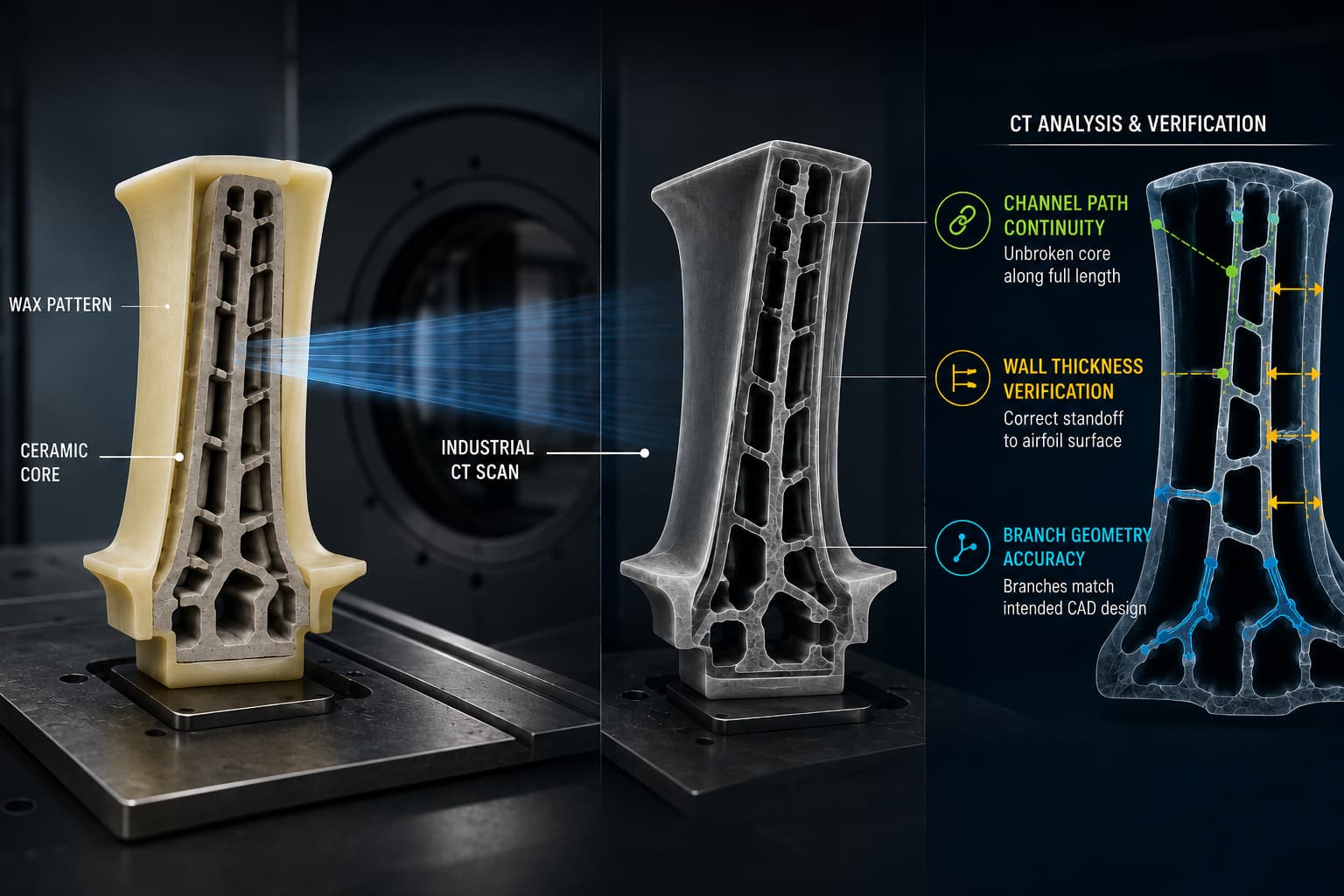
Conceptual illustration of CT scanning a turbine blade wax pattern and ceramic core before casting, verifying cooling channel path, wall thickness, and branch geometry, used to explain turbine blade CT inspection and cooling channel inspection.
Why Verification Before the Pour Changes the Economics of a Defect
Most aerospace turbine blade CT inspection discussions focus on the finished part. But by the time a cast blade with a collapsed cooling channel reaches final inspection, the manufacturer has already spent the full cost of casting, machining, and coating a part that was defective from the pattern stage. Non-destructive evaluation applied to the wax pattern and ceramic core, before the pour, catches the same class of defect at a fraction of the cost, since the only investment lost is the pattern and core, not the finished casting.
What Cooling Channel Inspection Verifies
Cooling channel inspection at the stage before casting checks three things a visual check of the pattern can not confirm reliably:
- Channel path continuity. Confirming the core geometry that will form the cooling channel is unbroken along its full length, since even a fine core fracture becomes a blocked or restricted channel in the finished blade.
- Wall thickness between channel and airfoil surface. Verifying the core sits at the correct standoff distance from the pattern’s outer wall, since a shifted core creates a wall too thin in one area and too thick in another.
- Channel cross section and branching geometry. Confirming cooling designs with multiple branches, common in modern turbine blades that operate under high pressure, match the intended CAD geometry rather than a distorted or partially fused core structure.
Verification Target | Consequence If Missed | Detection Method |
Core fracture or discontinuity | Blocked cooling channel, localized overheating in service | CT scan of ceramic core prior to shell investment |
Core shift or misalignment | Uneven wall thickness, localized thermal stress | CT dimensional comparison against CAD |
Branch geometry deviation | Reduced or uneven cooling flow | CT cross section at branch junctions |
Why This Matters More Before Casting Than After
Internal channel analysis performed after casting still works, and XRAY-LAB has detailed the volumetric CT approach behind it in how PolyCT is transforming aerospace CT inspection. But catching a core defect after the pour means the metal, the machining time, and the coating process are already sunk costs. Inspecting the pattern and core before the pour shifts detection to the point where the only loss is the pattern itself, the same logic behind catching a defect at its earliest possible process stage rather than at final inspection, a principle XRAY-LAB has also applied to aluminum die casting quality, where feeding inspection data back to an earlier process stage reduces scrap cost across the industry, not just in aerospace.
Aerospace casting quality programs that skip verification before the pour often only discover a channel defect once a group of finished blades fails final CT, at which point the entire group’s tooling and core supplier need investigation, the same process for finding a root cause that XRAY-LAB has outlined in how CT scanning accelerates root cause failure investigations.
XRAY-LAB performs turbine blade CT inspection at both the stage before casting and on the finished part, giving manufacturers the option to catch cooling channel defects at whichever process stage minimizes scrap cost for their specific production volume.
Frequently Asked Questions
What is turbine blade CT inspection at the stage before casting?
It is CT scanning of the wax pattern and ceramic core used to form a turbine blade’s cooling channels, performed before metal is poured, to catch geometry defects while the only cost at risk is the pattern itself.
Why does cooling channel inspection matter before casting rather than after?
A defect caught at the pattern stage only costs the pattern and core. The same defect caught after casting has already consumed the metal, machining, and coating investment.
What does internal channel analysis check for in a turbine blade core?
Core fracture or discontinuity, core misalignment affecting wall thickness, and deviation in branch geometry from the intended cooling design.
How does non-destructive evaluation improve aerospace casting quality specifically?
By catching geometry defects at the earliest process stage, before they propagate into a full group of scrapped or field risk castings, reducing both cost and the scope of any resulting investigation.
Is inspection before the pour a replacement for turbine blade inspection after casting?
No. Most programs use both: checks before the pour catch pattern and core defects early, while CT after casting verifies the finished part’s full internal geometry and any casting stage defects.