Defects detected by CT scanning span a wide range of internal conditions, and no two defect types share exactly the same origin, appearance, or detection requirement. A nondestructive testing defect library organized by defect type, rather than by industry alone, gives quality engineers a faster way to set acceptance criteria and choose appropriate resolution, since the same defect category, porosity for example, behaves consistently whether it appears in a casting or an additively manufactured part. This comparison works through the major defect categories CT scanning defect detection covers, how each forms, and how CT identifies it.
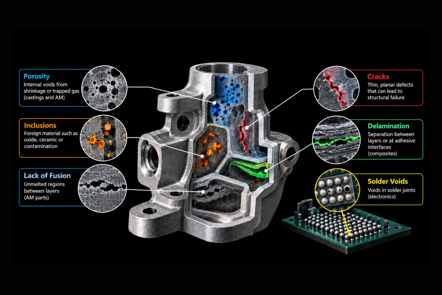
3D CT reconstruction showing how volumetric inspection reveals diverse internal defect morphologies across cast, additive-manufactured, composite, and electronic components.
Porosity Detection With CT Across Casting and AM
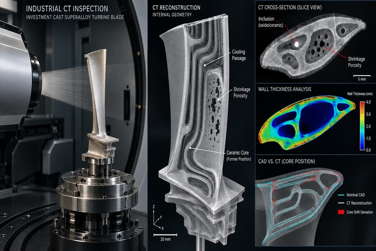
Porosity is internal void formation, and it appears through different mechanisms depending on the manufacturing process. In casting, shrinkage porosity forms as metal cools and contracts near the last regions to solidify, while gas porosity results from trapped gas in the melt. In additive manufacturing, porosity typically arises from insufficient laser energy density or trapped shielding gas during the build. CT identifies porosity in both contexts by its rounded shape and characteristic density signature, though acceptance criteria for porosity size and distribution differ significantly between casting and AM applications, as reflected in CT inspection of sand-cast iron and steel parts.
Inclusion Detection X-Ray CT Reveals in Castings and Assemblies
Inclusions are foreign material embedded within a part during manufacturing, such as ceramic shell fragments in investment castings, oxide particles from the melt, or contamination introduced into a raw material feedstock before processing even begins. Inclusion detection X-ray CT separates inclusions from porosity using density contrast rather than shape alone, since both defect types can appear similarly rounded on a flat radiograph despite representing entirely different quality concerns. Contamination entering a material supply chain before manufacturing, such as the powder reuse risk covered in detecting powder contamination in 3D-printed titanium, is one specific pathway inclusions can take into a finished part.
Crack Detection CT Scanning and Lack-of-Fusion Detection AM CT
Cracks and lack-of-fusion defects share a planar, discontinuity-like geometry that distinguishes them from rounded porosity, and both behave like pre-existing stress concentrators once a part is placed under load. Crack detection CT scanning identifies these features by their thin, elongated profile and sharp density transition at the defect boundary. Lack-of-fusion detection AM CT specifically targets unmelted regions between adjacent layers or scan tracks in metal additive manufacturing, a defect mode that forms for entirely different process reasons than a casting crack but presents a comparably serious structural risk in service.
Voids and Delamination Detection CT in Electronics and Composites
Voids and delamination detection CT covers a different category of defect entirely, one rooted in bonding and assembly rather than solidification. Solder voids form during reflow in electronic assemblies, delamination occurs between composite plies or at adhesive interfaces, and both defects are frequently invisible from any external vantage point once the part is assembled. CT resolves these defects by reconstructing the internal bond line or joint directly, an approach applied specifically to electronics assemblies in micro-CT inspection of BGA and solder joint voids, where every joint in a dense array would otherwise overlap in a single 2D projection.
How CT Compares to Other NDT Methods Across Defect Types
No single NDT method detects every defect category equally well, and CT’s specific advantage is volumetric coverage: internal defects are located and sized in three dimensions rather than inferred from a surface indication or a flattened projection. Ultrasonic testing and dye penetrant remain effective and often faster for specific surface or near-surface applications, while radiography shares CT’s underlying physics but lacks its spatial resolution for complex geometries, a distinction covered directly in the difference between industrial X-ray and CT scanning. Selecting the right method, or combination of methods, depends on which defect category a program is actually trying to catch.
XRAY-LAB applies this same defect-category framework across the industries it serves, from casting porosity and AM lack-of-fusion to electronics voids and composite delamination. Organizing inspection findings by defect type rather than by a single industry vertical allows lessons learned in one application, such as inclusion separation techniques developed for castings, to transfer directly to a completely different material and process where the same underlying defect signature appears.
Frequently Asked Questions
What types of internal defects can CT detect across different materials?
CT detects porosity, inclusions, cracks, lack-of-fusion, voids, and delamination across metals, composites, and electronic assemblies, identifying each by a distinct combination of shape, density signature, and spatial location.
Can CT detect both surface and subsurface defects in one scan?
CT detects both surface and subsurface defects in a single scan, since the technique reconstructs the entire part volume rather than examining the surface and interior through separate methods.
How does CT compare to ultrasonic, radiography, and dye penetrant for defect detection?
CT offers volumetric, three-dimensional defect location that ultrasonic, radiography, and dye penetrant do not fully replicate, though those methods can be faster or more practical for specific surface-level applications.
What is the smallest defect size CT can reliably detect?
Reliable detection generally requires a defect to span several voxels in the reconstructed dataset, so the smallest detectable defect size depends directly on the voxel size the scan configuration achieves.
How are CT defect data used for root cause analysis and process improvement?
CT defect data supports root cause analysis by correlating defect type, size, and location with specific process parameters, tooling, or material batches, allowing manufacturers to address the underlying cause rather than sorting defective parts after the fact.