Aluminum die castings form the core of modern vehicle architecture; subframes, control arms, battery enclosures, and structural brackets are increasingly cast rather than stamped or forged, largely because casting enables detailed geometries to be produced in a single shot with reduced assembly weight. That same complexity, however, is what makes internal quality difficult to guarantee. A die-cast part can look flawless on the outside while carrying gas porosity, shrinkage cavities, or cold shuts buried deep inside its wall sections, and none of these defects announces themselves until the part is under load.
Traditional quality checks-visual inspection, dye penetrant testing, or destructive sectioning of sample parts- were built around the assumption that surface condition is a reasonable proxy for internal condition. For die castings, that assumption breaks down quickly. Industrial CT scanning fills this gap by reconstructing the complete internal geometry of a cast part in three dimensions, without cutting, drilling, or otherwise compromising the sample.
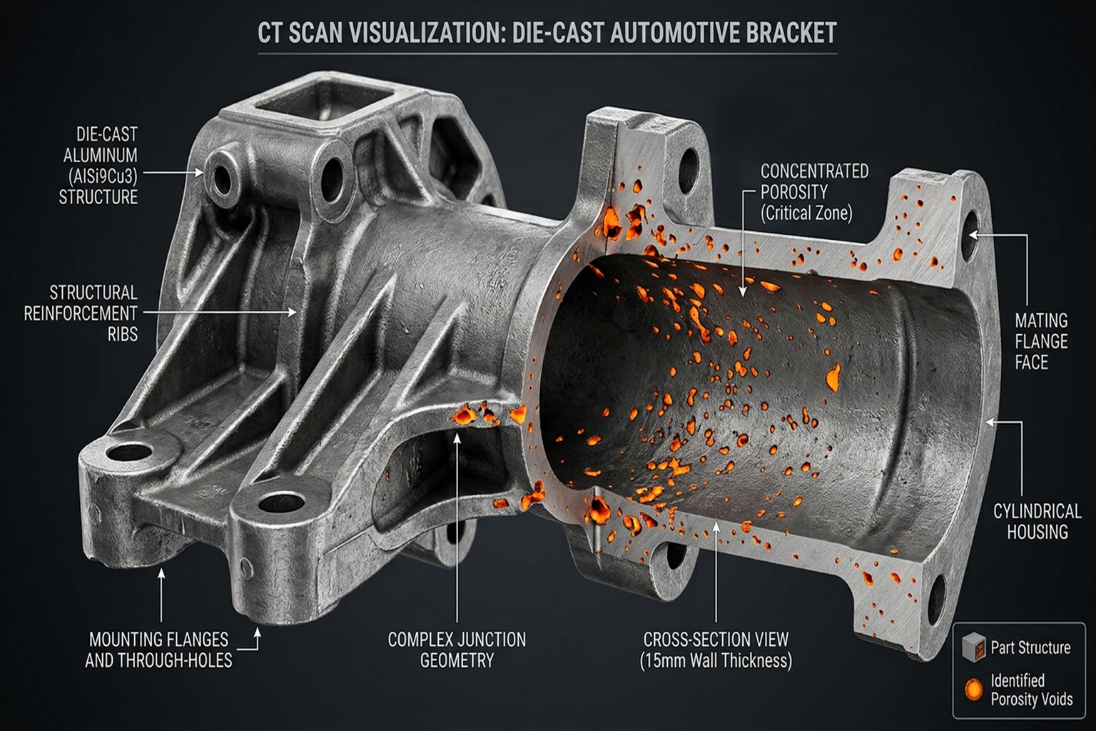
A cutaway CT rendering of an aluminum automotive structural casting showing internal porosity clusters highlighted in a contrasting color against the solid metal structure.
What Industrial CT Reveals Inside a Die-Cast Structural Part
A single CT scan produces a volumetric dataset that engineers can slice at any angle, allowing direct comparison to the original CAD model. For structural automotive castings, this typically uncovers:
- Gas porosity-trapped air or entrained gas forming small spherical voids, often concentrated near thick-to-thin wall transitions.
- Shrinkage porosity-irregular voids formed as molten aluminum solidifies and contracts, usually found in the thickest sections of a casting.
- Cold shuts-incomplete fusion between two flow fronts of metal, creating a hidden line of weakness
- Inclusions-oxide films or foreign material trapped within the casting during the pour.
- Wall thickness deviations-localised thinning that reduces load-bearing capacity without any visible external sign.
Because CT captures density variation throughout the entire volume rather than a single plane, it is one of the few methods capable of distinguishing between porosity that is cosmetically acceptable and porosity that compromises structural performance. This makes it especially useful for aluminum die castings, which share several qualification challenges with aluminum castings used in e-mobility applications, where structural dependability under load is equally critical.
Typical Scan Parameters for Structural Castings
Aluminum has a relatively low atomic number, which makes it more penetrable than steel or titanium, but structural castings are often thick and geometrically complex, calling for careful selection of tube voltage, scan time, and resolution.
Parameter | Typical Range | Notes |
Tube voltage | 150–300 kV | Higher end used for thick-walled subframe and battery housing castings |
Voxel resolution | 20–80 µm | Finer resolution for thin-wall sections near load paths |
Scan duration | 20 minutes–2 hours | Depends on part size and required resolution |
Defect detectability | Down to ~10–15 µm | Sufficient to flag micro-porosity clusters before they propagate |
Porosity Severity: A Practical Way to Read the Results
Not every void found in a CT scan warrants rejection. Engineers typically classify porosity by size, location, and proximity to critical load paths, rather than by existence alone.
Porosity Class | Void Size | Typical Location Risk | Action |
Cosmetic | <0.5 mm | Non-load-bearing zones | Accept |
Moderate | 0.5–2 mm | Mid-wall, away from stress risers | Monitor/trend |
Critical | >2 mm or clustered | Near fillets, bolt bosses, thin-to-thick transitions | Reject |
This kind of classification allows manufacturers to set pass/fail criteria that reflect actual mechanical risk rather than reacting to every void a scan finds. In practice, it turns scan results into a more usable qualification framework.
Where This Matters Most in Vehicle Design
Structural die castings are now common in suspension mounts, motor housings, and, increasingly, large single-piece body structures used in electric vehicles. In each case, the part sits directly in a load path where a hidden defect can translate into a fatigue crack after thousands of drive cycles. This is why CT-based qualification during development and periodic sampling during production allow manufacturers to catch process drift, a shift in mold temperature or fill speed, for example, before it results in a field failure. This approach resembles the inspection principles used in metal additive manufacturing, where internal structural strength is equally non-negotiable.
Conclusion
Industrial CT scanning for aluminum die casting inspection provides automotive manufacturers with conventional inspection: a complete, measurable view of a casting’s internal condition without destroying the part. As structural castings take on a larger share of vehicle architecture, this level of internal visibility is becoming less of an advantage and more of a baseline expectation for safety-critical components. XRAY-LAB supports manufacturers through this shift by providing the scanning exactness and reporting clarity essential to qualify structural castings with confidence, from early design validation up to production sampling.
Frequently Asked Questions
Can CT scanning replace destructive sectioning for die casting qualification?
For most porosity and inclusion analysis, yes. Destructive sectioning is still occasionally used to correlate CT findings with metallurgical structure, but it no longer needs to be the primary method of qualification.
How thick can a casting be effectively inspected with industrial CT?
Modern systems can penetrate wall sections found in most automotive structural castings, though very thick or dense sections may require higher tube voltages and longer scan times.
Does CT scanning damage the part?
No. CT scanning is entirely non-destructive; the part can be returned to service or continue through the production or testing process afterwards.
What is the difference between shrinkage porosity and gas porosity in a CT scan?
Shrinkage porosity typically appears irregular and concentrated in thick sections, while gas porosity appears more spherical and can occur throughout the casting.
Is CT scanning practical for 100% production inspection of die castings?
It is more commonly used for sampling, first article inspection, and failure analysis, though high-throughput inline CT systems are increasingly used for critical structural parts.