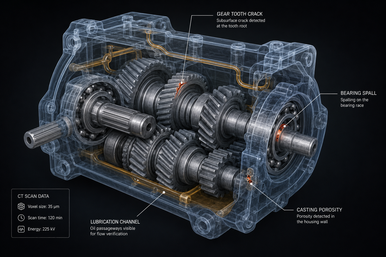
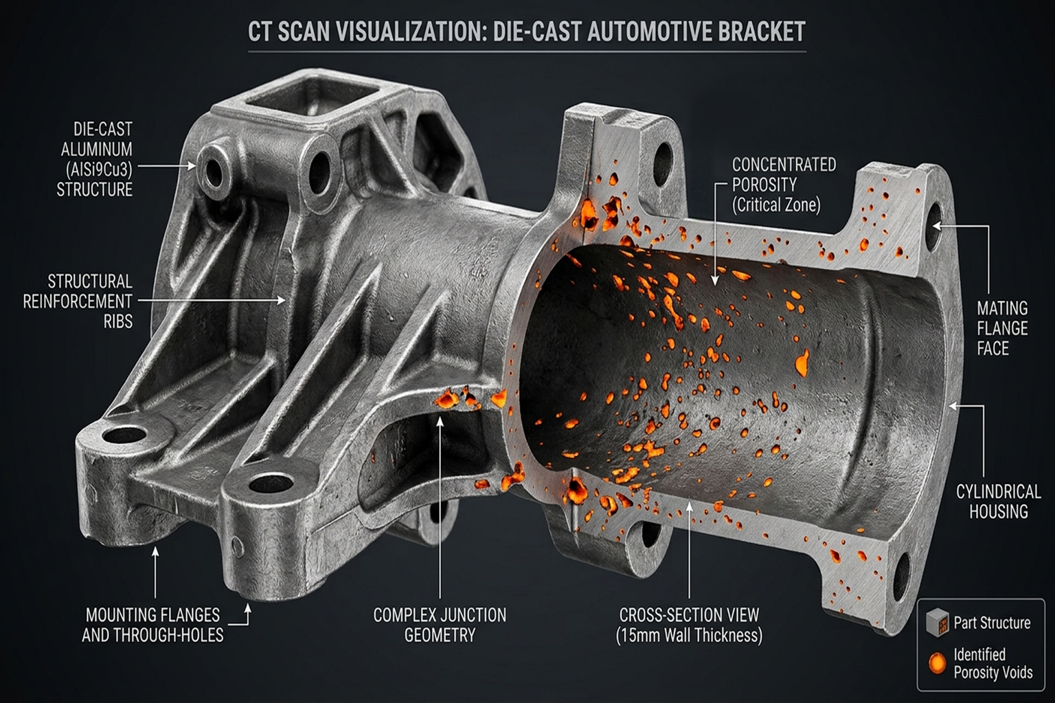
A robotic actuator looks simple from the outside: a compact housing, a motor, and a shaft that rotates or extends. Inside, it is one of the most densely packed assemblies in modern manufacturing; precision gears, bearings, encoders, wiring harnesses, and sealing components are all stacked into a space with almost no tolerance for misalignment. When a robotic arm repeats the same motion thousands of times a day, even a microscopic defect in one of its internal components can eventually lead to a positioning error, a vibration issue, or a full mechanical failure.
Because actuators are sealed units, opening one to inspect it typically destroys the assembly or, at minimum, disturbs the very alignment that needs to be verified. Industrial CT scanning solves this by allowing every internal component to be examined in place, in its normal operating position, without disassembly, the same non-destructive advantage that makes CT valuable for mechanical switch inspection, where internal contacts and springs must also be evaluated without disturbing their configuration.
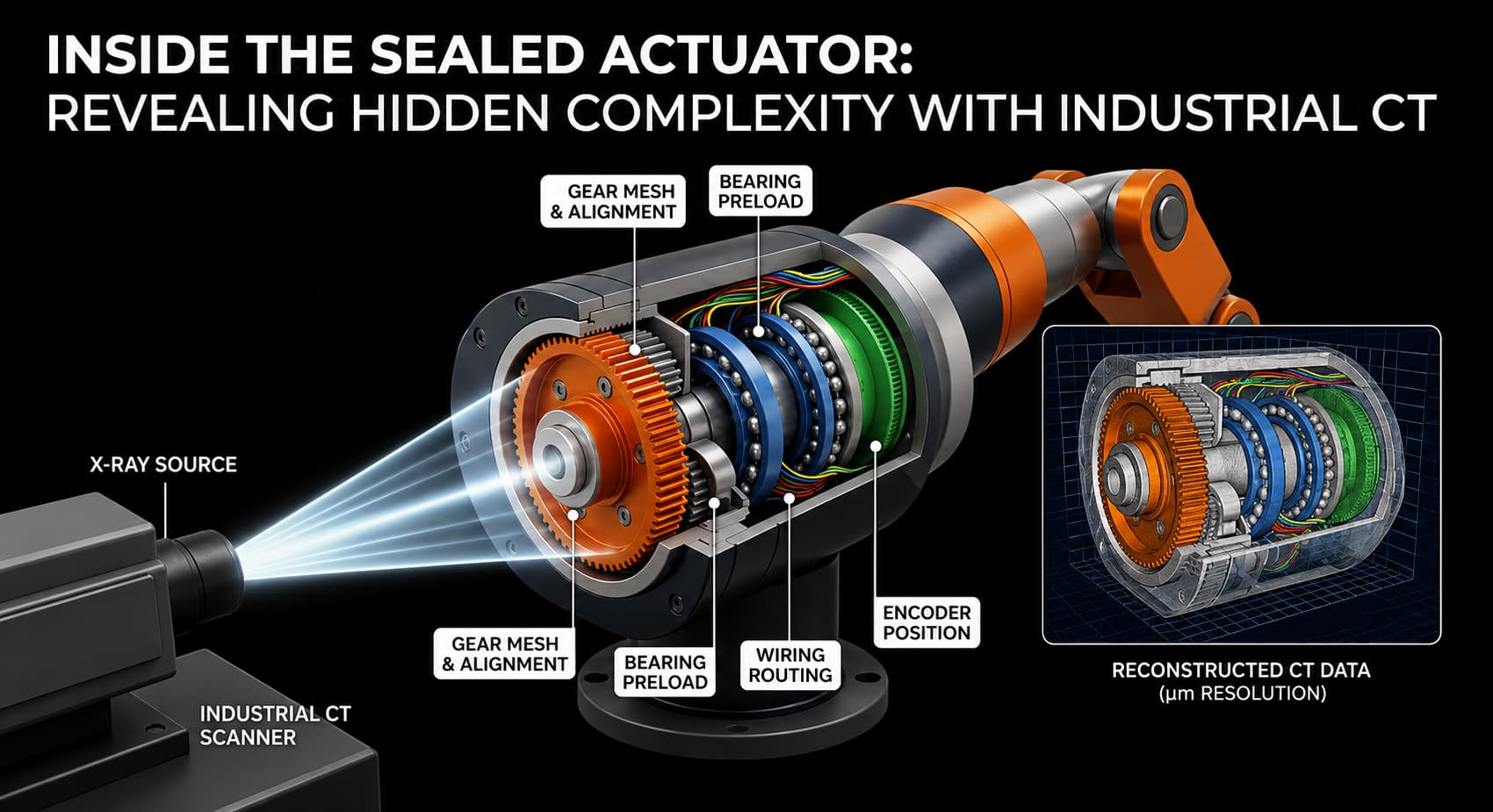
An inside look at non-destructive testing: How industrial CT scanning maps the complex internal components of a sealed robotic actuator, from gear mesh to wiring paths, in 3D.
Robotic actuator CT scanning: How the CT Inspection Process Works for Actuator Assemblies
- Fixturing-the actuator is mounted to minimize movement during rotation, since even slight vibration can blur fine internal features
- Scan parameter selection-tube voltage and resolution are set based on the densest material present (steel bearings and gears typically require higher penetration than the aluminum or polymer housing)
- Data acquisition-hundreds to thousands of projection images are captured as the part rotates
- Reconstruction-the projections are combined into a full 3D volumetric model
- Analysis-engineers review internal alignment, gear mesh, bearing condition, wiring routing, and seal integrity against the reference design
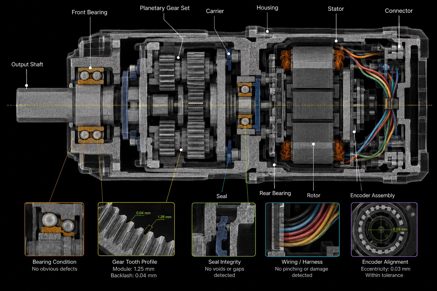
Industrial CT cross-sectional view of a sealed robotic rotary actuator showing the internal planetary gear set, precision bearings, electric motor, encoder assembly, wiring harness, seals, and output shaft. The non-destructive scan enables verification of gear alignment, bearing condition, wiring integrity, and encoder positioning without disassembling the actuator.
Defects Commonly Found Inside Actuator and Joint Assemblies
Component | Typical Defect Found | Consequences if Undetected |
Bearings | Micro-cracking, improper preload, contamination | Premature wear, vibration, noise |
Gear sets | Tooth chipping, misalignment, insufficient mesh | Backlash, positioning error |
Wiring/harness | Pinched wires, incorrect routing, insulation damage | Intermittent faults, short circuits |
Encoder assembly | Misalignment relative to shaft | Inaccurate position feedback |
Seals and housings | Voids, incomplete bonding | Lubricant leakage, contamination ingress |
Wiring and harness defects inside an actuator are conceptually similar to the internal wire-terminal issues addressed through crimp connection inspection, where CT is used to verify strand behavior and contact integrity that cannot be assessed from the outside.
Resolution Requirements by Component Type
Because actuators combine coarse structural parts with extremely fine internal features, scan resolution needs to be carefully matched to the item being inspected.
Feature Being Inspected | Recommended Voxel Resolution | Reasoning |
Housing and structural elements | 40–80 µm | Sufficient for wall thickness and casting checks |
Gear teeth and bearing races | 10–25 µm | Needed to detect fine chipping or race spalling |
Wiring and connector pins | 5–15 µm | Fine detail required for insulation and contact checks |
Achieving this level of detail relies heavily on the same principles covered in microfocus X-ray technology, where a smaller focal spot directly improves the sharpness of fine internal features.
Why This Matters for Industrial and Collaborative Robotics
As robotic joint arms move into higher-precision applications- surgical robotics, semiconductor handling, and collaborative manufacturing cells working alongside people- the tolerance for undetected internal defects shrinks considerably. A gearbox with a small alignment issue may not fail outright, but it can introduce positioning drift that compounds over millions of cycles. CT inspection during design validation and failure analysis enables engineers to catch this before it becomes a warranty claim or, in safety-critical applications, a hazard.
Conclusion
Industrial CT inspection of mechanical gearbox assemblies and precision mechanical assemblies gives engineers a way to see problems developing inside a sealed housing long before they show up as noise, vibration, or failure. As gearboxes are asked to do more with tighter tolerances and longer service intervals, this kind of internal visibility is becoming a standard part of both design validation and quality assurance programs. XRAY-LAB brings this capability to manufacturers evaluating gearbox designs or investigating in-service failures, translating raw scan data into insight that supports real engineering decisions.
Frequently Asked Questions
Can CT scanning detect gear misalignment inside a sealed actuator?
Yes. Because CT reconstructs the full 3D geometry, gear mesh and shaft alignment can be measured directly from the scan data and compared to design tolerances.
Is it possible to inspect an actuator while it is partially assembled?
Yes, CT scanning does not require disassembly, which is one of its main advantages for sealed or potted components.
How long does a typical actuator CT scan take?
Scan time varies with size and required resolution, but most actuator assemblies can be scanned and reconstructed within one to a few hours.
Can CT inspection be used for warranty return analysis?
Yes, it is commonly used to determine the root cause of a failed actuator without cutting it open, preserving evidence for supplier discussions.
Does the presence of both metal and plastic components affect scan quality?
It can, since materials with very different densities require careful parameter tuning, but modern CT systems routinely handle mixed-material assemblies.