A solid turbine blade scans in a predictable amount of time. An additively manufactured blade with an internal lattice structure, designed for weight reduction and optimized cooling channels, does not. Every strut, node, and internal void in that lattice adds geometric complexity that a standard CT scan strategy has to resolve, and resolving fine internal geometry generally means more projections, longer exposure per projection, or both. The result is that lattice structure analysis on a genuinely complex AM part can take significantly longer to scan than a solid part of the same external size, even though the lattice itself uses less material.
This is not a limitation of CT as a technology. It’s a limitation of applying a generic scan strategy to a part geometry that doesn’t behave like a generic part.
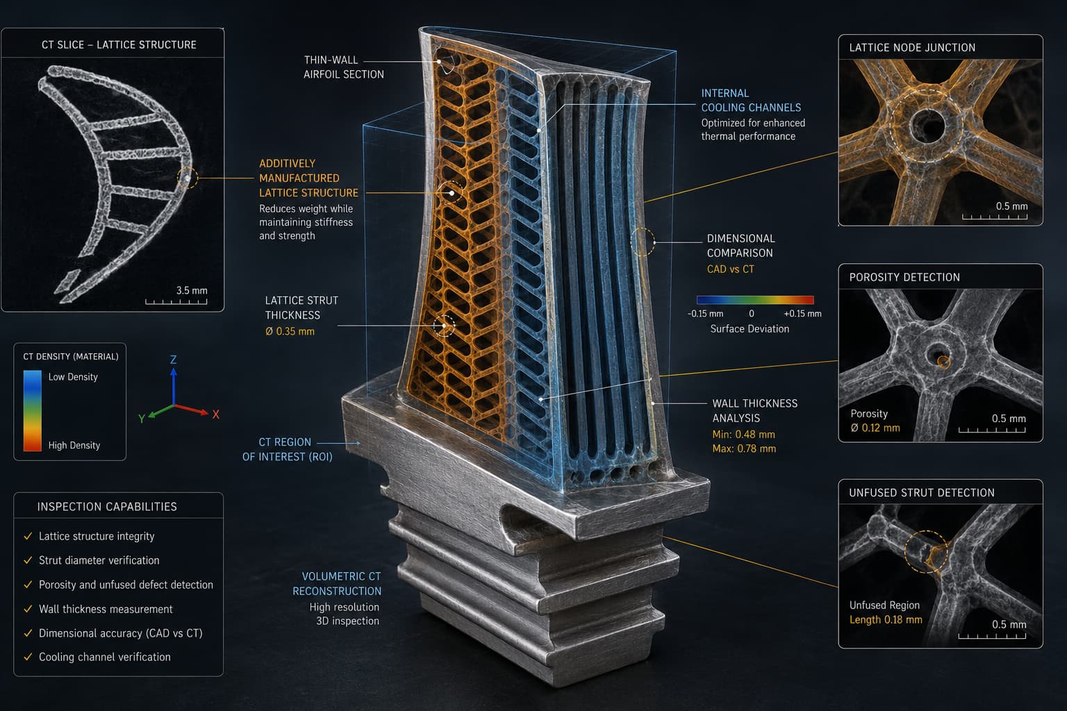
Conceptual illustration of a CT scan on a 3D-printed turbine blade lattice structure, with inset views of node junctions, porosity, and unfused struts, used to explain turbine blade CT inspection and lattice structure analysis.
Determinants of CT Scan Duration in Lattice Geometries
CT scan time is driven by three variables working against each other: resolution needed to resolve the smallest lattice strut, the number of projections needed to reconstruct that resolution without artifacts, and the exposure time per projection needed for adequate signal-to-noise. Pushing any one of these up to improve image quality drives total scan time up as well, often disproportionately for a fine lattice compared to a solid part.
Scan Time Driver | Effect on a Solid Part | Effect on a Lattice Structure |
Voxel resolution required | Set by wall thickness or feature size | Set by strut diameter, often finer |
Number of projections | Standard for part diameter | Often increased to resolve overlapping struts |
Exposure per projection | Set by material density | Higher if struts sit at multiple depths |
Reconstruction complexity | Straightforward | Higher, more internal surfaces to resolve |
Optimizing Scan Strategy Without Reducing Detection Confidence
The lever that matters most isn’t brute-force resolution, it is matching the scan strategy to what the part actually needs checked. This is the same principle behind XRAY-LAB’s approach to PolyCT’s cost reduction on high-density components, where scan-strategy optimization, not just faster hardware, is what compresses inspection time by a significant margin. For a turbine blade lattice, that means defining upfront which defect types actually matter (unfused struts, porosity at node junctions, dimensional deviation from the design lattice) and building the scan protocol around resolving those specifically, rather than maximizing resolution across the entire volume uniformly.
Industrial CT scanning strategies built this way typically separate the lattice region from any solid shell or root section of the blade, applying finer resolution only where the lattice geometry demands it and a faster, coarser pass where the part is solid. This targeted approach is directly applicable to the broader aerospace inspection challenge XRAY-LAB has addressed in how PolyCT is transforming aerospace CT inspection, where reducing scan time without reducing detection confidence is the core engineering problem across component types, not just lattices.
Implications for Aerospace Qualification Standards
Aerospace quality inspection standards generally require complete internal verification, not sampling, for flight-critical components like turbine blades. That requirement doesn’t change based on how long the scan takes, which means scan time reduction isn’t an optional efficiency gain. It is what determines whether 100% CT inspection of a lattice component is economically viable in production at all. A scan strategy that takes hours per part effectively rules out full inspection at production volume; one that takes minutes does not.
When a lattice defect does slip through and surfaces later as a field failure, the same volumetric data that would have caught it during qualification is what a root-cause team needs to trace it back to origin, the process XRAY-LAB outlines in how CT scanning accelerates root cause failure investigations.
XRAY-LAB performs turbine blade CT inspection using scan strategies built specifically around lattice geometry, separating fine internal structures from solid regions to keep full-volume verification practical at the throughput aerospace production actually requires.
Frequently Asked Questions
Why does CT scan for additive manufacturing take longer on lattice structures?
Fine internal struts require higher resolution and often more projections to reconstruct without artifacts, which increases total scan time compared to a solid part of similar size.
What defects does turbine blade CT inspection typically look for in a lattice?
Unfused or partially fused struts, porosity concentrated at node junctions, and dimensional deviation from the intended lattice geometry.
Can lattice structure analysis be done without scanning the entire part at maximum resolution?
Yes. Applying finer resolution only to the lattice region and a faster pass to solid sections significantly reduces total scan time without reducing defect detection where it matters.
Is industrial CT scanning required for every AM turbine blade, or is sampling acceptable?
Flight-critical aerospace components generally require full internal verification rather than statistical sampling, given the consequence of an undetected defect.
How does aerospace quality inspection factor scan time into production feasibility?
Scan time directly determines whether 100% CT inspection is practical at production volume; a strategy that takes too long per part can make full verification economically unworkable.