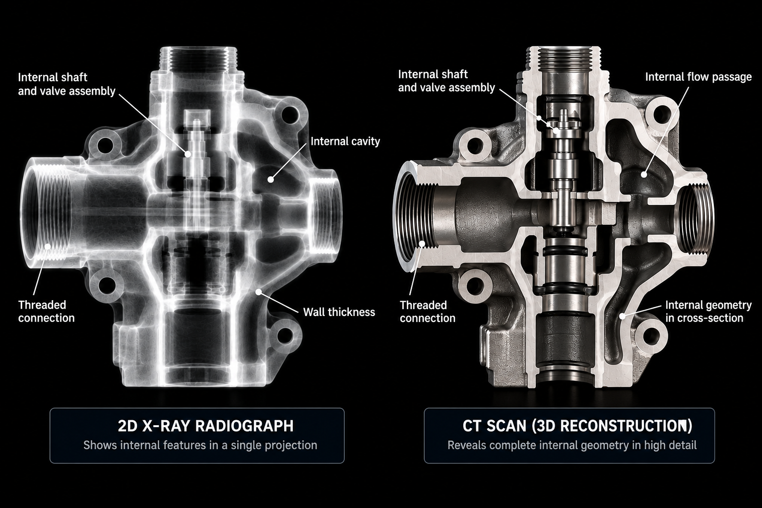
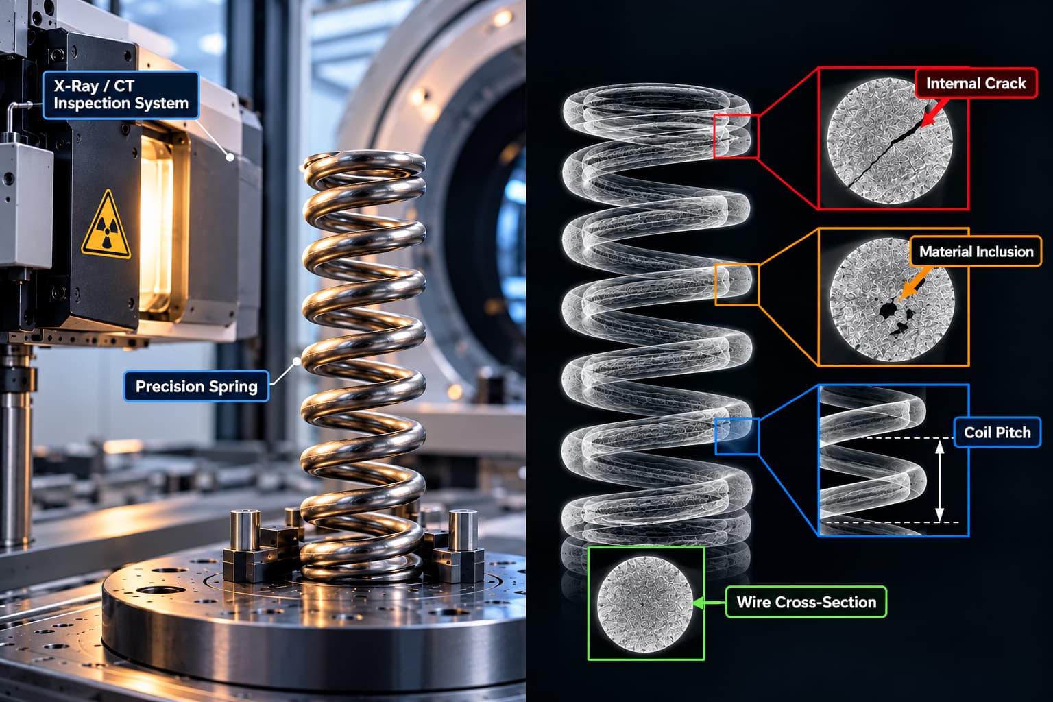
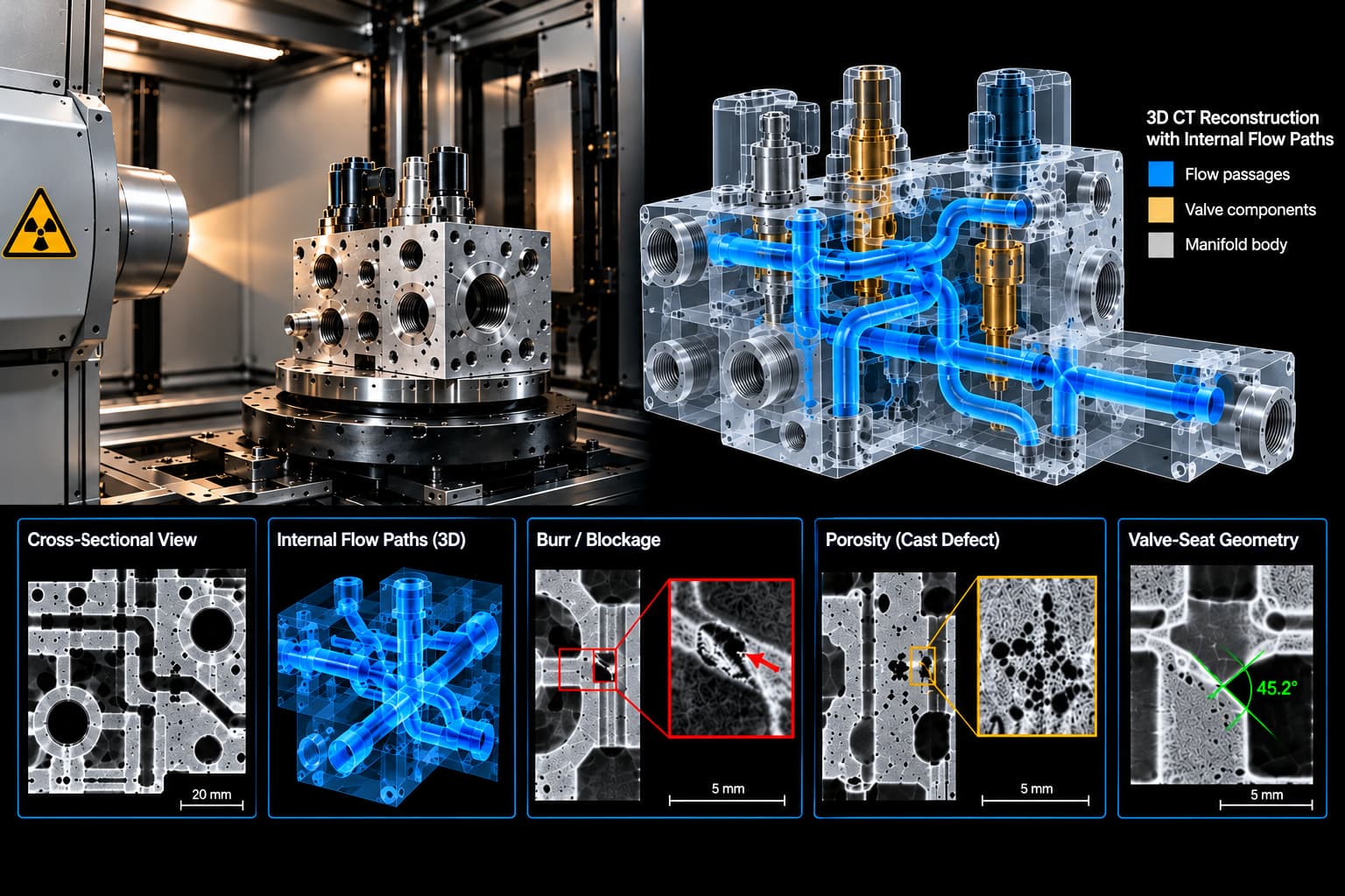
A fuel injector can leave the production line within specification and still fail early in service, losing spray precision as coking deposits build up inside its nozzle. Injector nozzle inspection NDT has historically relied on flow bench testing and destructive sectioning to characterize this kind of degradation, both of which either measure the symptom rather than the cause or destroy the part in the process of understanding it. CT scanning resolves fuel injector inspection at the source, by capturing internal geometry and internal condition together in one nondestructive scan.
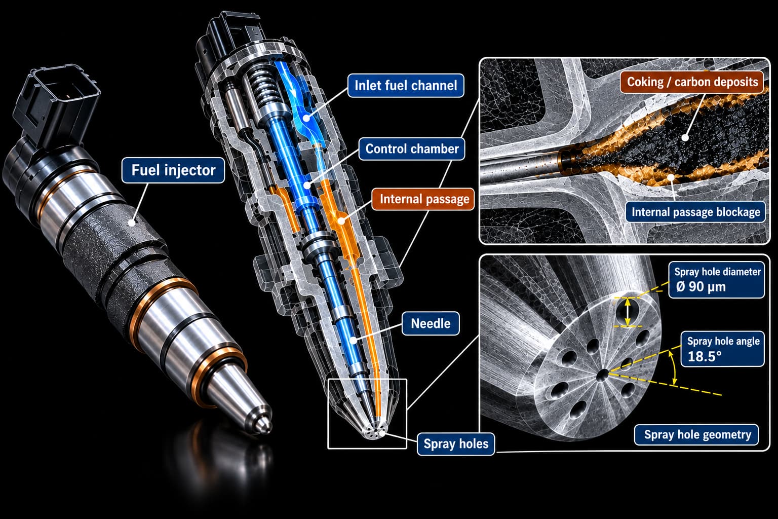
CT inspection of a fuel injector revealing internal passages, spray-hole geometry, and coking-related blockage for nondestructive dimensional and defect analysis.
The Problem: Fuel Injectors That Fail Without Warning
Fuel injector performance depends on spray hole geometry measured in tens to hundreds of microns, and any deviation in hole diameter, angle, or roundness directly changes atomization quality and, in turn, combustion efficiency and emissions. Over time, coking deposits and internal passage blockage narrow these same passages gradually, so a diesel injector or gasoline direct injector can drift out of acceptable spray performance well before any external symptom becomes obvious to an operator. Flow testing catches the downstream effect, reduced or uneven flow, but it does not show where inside the injector the restriction is actually occurring.
Solving the Resolution Problem: Measuring Spray Hole Geometry With CT
Spray hole inspection at the sub-hundred-micron scale requires imaging resolution well beyond what conventional radiography provides, which is where microfocus X-ray technology becomes essential. A small focal spot size reduces geometric distortion enough to resolve individual spray hole diameter, entrance angle, and inlet corner geometry directly from the CT dataset, giving CT for fuel injector nozzle geometry the precision needed to detect deviation that would otherwise only surface as an inconsistency in downstream spray pattern testing.
Solving the Detection Problem: Identifying Coking and Deposits Inside Nozzles
Spray hole coking detection CT distinguishes carbon deposit buildup from the surrounding nozzle material based on density contrast, revealing the deposit’s exact location and thickness along the internal passage rather than only its downstream effect on flow. This same volumetric approach to separating internal material from an unwanted internal feature is a principle shared with high-resolution inspection of other compact, feature-dense components, such as the small-scale internal structures examined in high-resolution micro-CT for PCB connectors, where distinguishing intended material from contamination at a similarly fine scale is central to the inspection task.
Solving the Blockage Problem: Quantifying Internal Passage Blockage With CT
Internal passage blockage in injectors CT is quantified by comparing the as-scanned internal channel geometry against its nominal cross-sectional area, producing a direct measurement of flow-area reduction rather than an inferred one. This comparison follows the same principle used in wall thickness analysis with industrial CT, where internal geometry is measured directly against a reference rather than estimated from an external proxy, allowing X-ray CT for diesel injector nozzles to report partial blockage as a specific percentage of flow-area loss.
Solving the Production Problem: CT in Injector R&D Versus Production QA
Fuel injector deposit analysis using CT plays a different role depending on program stage. In research and development, full-resolution CT scans support detailed characterization of new nozzle designs and coking behavior under varying fuel and operating conditions. In production quality control, faster, targeted CT scans focused on critical spray hole dimensions support sampling-based verification without the full analysis depth an R&D scan requires, a production-scale inspection approach paralleled in CT scanning for e-mobility components, where similar internal-channel verification supports high-volume manufacturing rather than one-off characterization.
XRAY-LAB applies this same combination of high-resolution geometry measurement and internal condition analysis to fuel injector and nozzle inspection programs, supporting both development-stage characterization and production sampling. The consistent customer outcome across these programs is a direct answer to where, exactly, an injector’s performance is degrading internally, rather than an inference drawn from external flow behavior alone.
Frequently Asked Questions
How does CT measure spray hole geometry and deviations?
CT measures spray hole geometry by reconstructing the nozzle’s internal passages in three dimensions at microfocus resolution, allowing hole diameter, entrance angle, and roundness to be extracted directly and compared against nominal design values.
Can CT detect coking and deposits inside injector nozzles?
CT detects coking and deposits by identifying the density contrast between the carbon buildup and the surrounding nozzle material, showing the exact location and thickness of the deposit along the internal passage.
What is the smallest internal passage or hole that CT can reliably inspect?
Microfocus CT systems can reliably resolve passages and spray holes in the tens-of-microns range, though achievable resolution depends on the specific system, part material, and overall part size being scanned.
How is CT used in injector R&D versus production quality control?
In R&D, CT supports full-resolution characterization of new nozzle designs and deposit behavior; in production, CT is typically applied as a faster, targeted scan focused on critical dimensions for sampling-based verification.
Can CT quantify partial blockages and flow-area reduction in nozzles?
CT quantifies partial blockage by comparing the as-scanned internal cross-sectional area against the nominal design area, reporting flow-area reduction as a specific percentage rather than an inferred estimate.