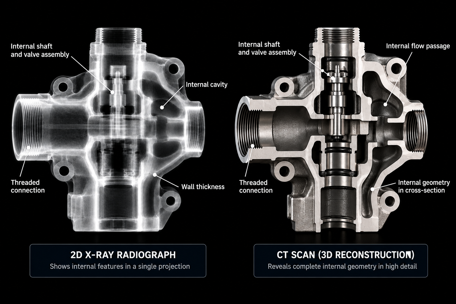
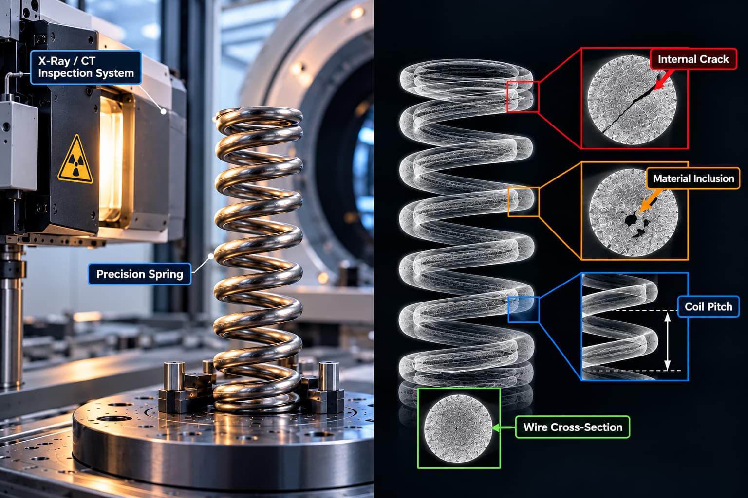
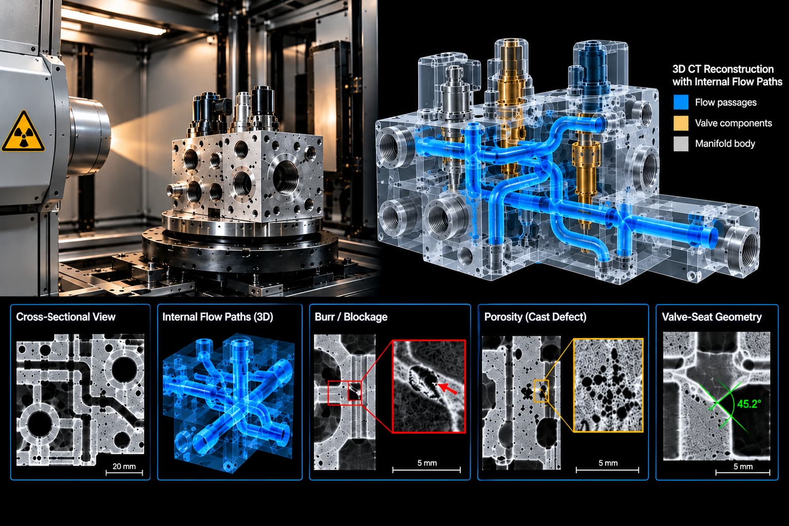
A battery pack enclosure that clears its manufacturing leak test is not guaranteed to remain sealed over its service life. Standard leak tests confirm the absence of a detectable leak at the pressure and moment of testing, but they do not rule out a marginal defect capable of developing into a leak path under sustained vibration and thermal cycling. This raises a fundamental diagnostic question: if the part cleared qualification, where did a later ingress path originate?
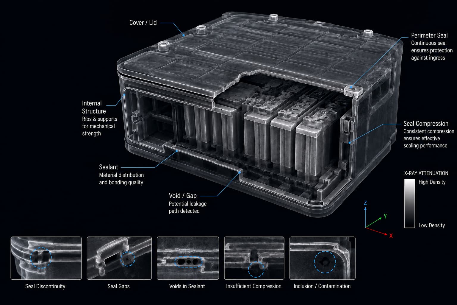
CT inspection reveals hidden sealing defects, voids, gaps, and compression issues inside battery pack enclosures—without disassembly.
Where battery enclosure leaks originate
There are three possible answers, and they require different inspection approaches.
The casting wall itself. Die-cast aluminum enclosures carry porosity from the casting process. Most of it is isolated and harmless. The failure mode is porosity that connects, a chain of small pores linking the inside of the wall to the outside, forming a through-wall leak path invisible from the surface. XRAY-LAB has documented this exact mechanism in aluminum die castings for automotive structural parts; an enclosure wall is the same material and process, with a much less forgiving consequence when porosity connects.
The weld seam. A cold weld, where the joint looks fused on the surface but has an internal gap, can pass a visual check and a light pressure test while still allowing slow ingress under vibration and thermal cycling over months.
The gasket interface. Uneven compression across the gasket, from a warped mating surface or an assembly torque inconsistency, leaves a narrow channel that a static pressure test may not catch but that opens under road flex.
Observed Symptom | Probable Defect Source | Confirmation Method |
Moisture near coolant lines, no external damage | Casting wall porosity | CT void mapping of wall thickness |
Slow ingress appearing only after months in service | Cold weld or seam gap | CT cross-section of the weld joint |
Leak correlating with vibration or road flex | Uneven gasket compression | CT imaging of the gasket interface under compression |
How CT inspection confirms and localizes the defect
The enclosure passed a helium or pressure decay leak test at manufacturing. That test answers one question: was there a leak large enough to detect at that moment, at that pressure. It does not answer where a marginal defect is, or whether nearby porosity is likely to grow into a leak path once the part starts flexing and cycling in the field. This is the gap leak detection CT scan inspection is built to close, by imaging the full wall, weld, and gasket volume in three dimensions rather than testing for pressure change alone.
Resolution requirements scale with the defect size a program needs to catch, which is why industrial computed tomography settings differ between routine production sampling and a root-cause investigation:
Target defect size | Recommended CT voxel resolution | Typical inspection stage |
>0.6mm (through-wall risk) | 50–100µm | Production sampling |
0.3–0.6mm (connected porosity) | 20–50µm | Qualification of new tooling |
<0.3mm (isolated micro-pores) | 5–20µm | Root-cause investigation |
The size-to-risk relationship shown in the chart above (leak risk accelerating past roughly 0.3mm as pores connect) is why EV battery enclosure quality programs increasingly screen wall porosity as a qualification step, not just a final leak check. XRAY-LAB has covered the same size threshold behavior in porosity analysis using CT scanning. Once moisture is confirmed inside the compartment, the investigation doesn’t stop at the enclosure: coolant or humidity reaching the cells is a direct path to the internal short-circuit risk XRAY-LAB has covered separately for lithium-ion cells. Battery sealing inspection and cell-level inspection are two different problems that meet at the same failure.
XRAY-LAB runs battery pack enclosure CT inspection to check all three failure points, casting wall, weld seams, and gasket interfaces, in a single non-destructive scan, distinguishing isolated defects from connected leak paths before parts reach final assembly. The same approach scales to production volume through XRAY-LAB’s inline CT capability.
Frequently Asked Questions
What is battery pack enclosure CT inspection?
It is the use of industrial computed tomography to check an EV battery enclosure’s casting walls, welds, and gasket interfaces for defects that could compromise sealing.
How is leak detection CT scan inspection different from a helium leak test?
A helium leak test confirms whether a leak exists at test conditions. A leak detection CT scan locates the defect in three dimensions and shows whether nearby porosity is likely to become a leak path later.
Why does casting porosity matter for EV battery enclosure quality?
Isolated porosity is usually harmless, but connected porosity across the wall thickness creates a through-wall leak path even when the surface looks intact.
Can industrial computed tomography check welds and gaskets, not just the casting?
Yes. CT images the full joint cross-section, so weld seams and gasket compression zones can be checked without cutting the enclosure open.
Does battery sealing inspection connect to cell-level failure risk?
Yes. Moisture or coolant entering through an enclosure defect is a direct path to internal short-circuit risk at the cell level.