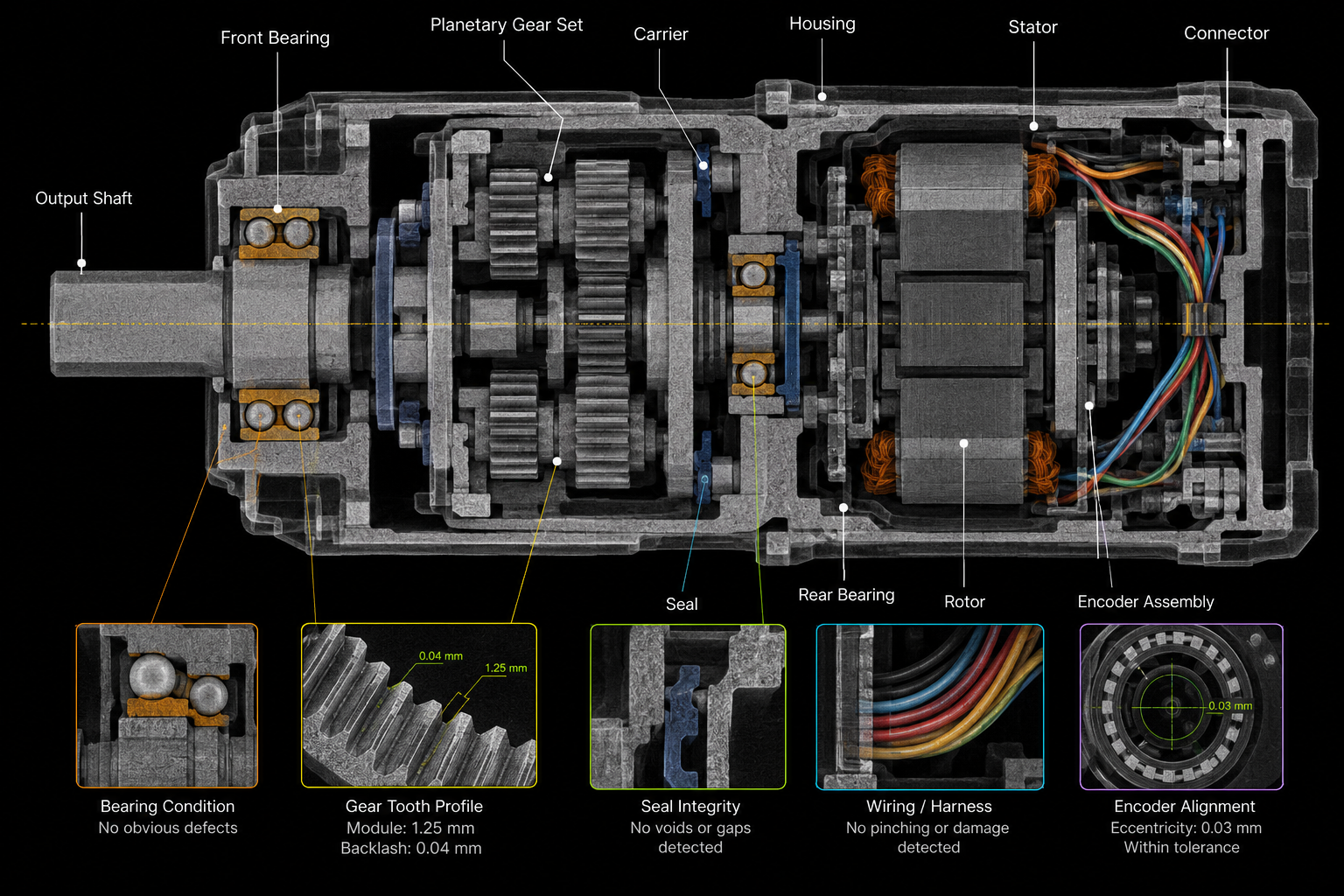
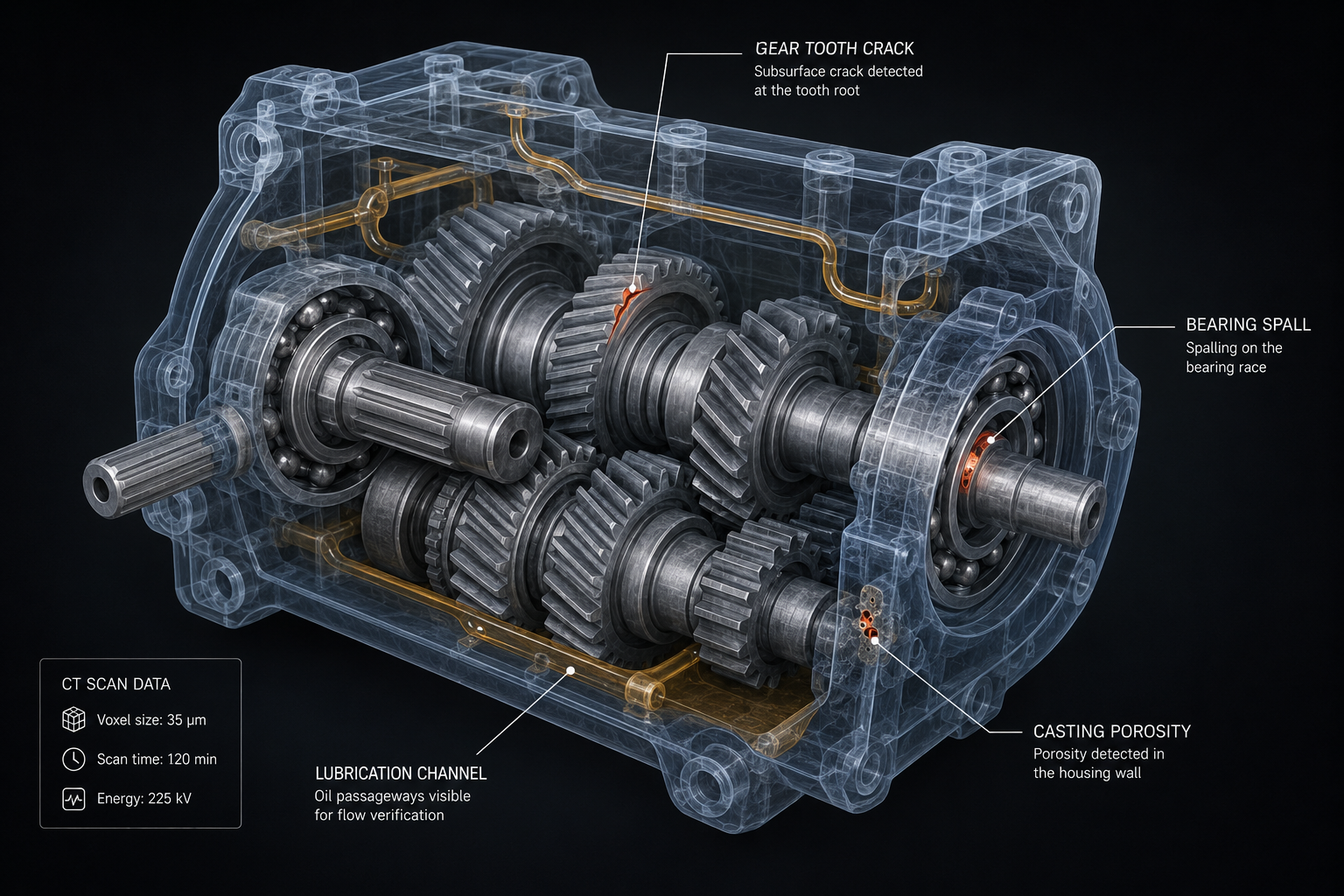
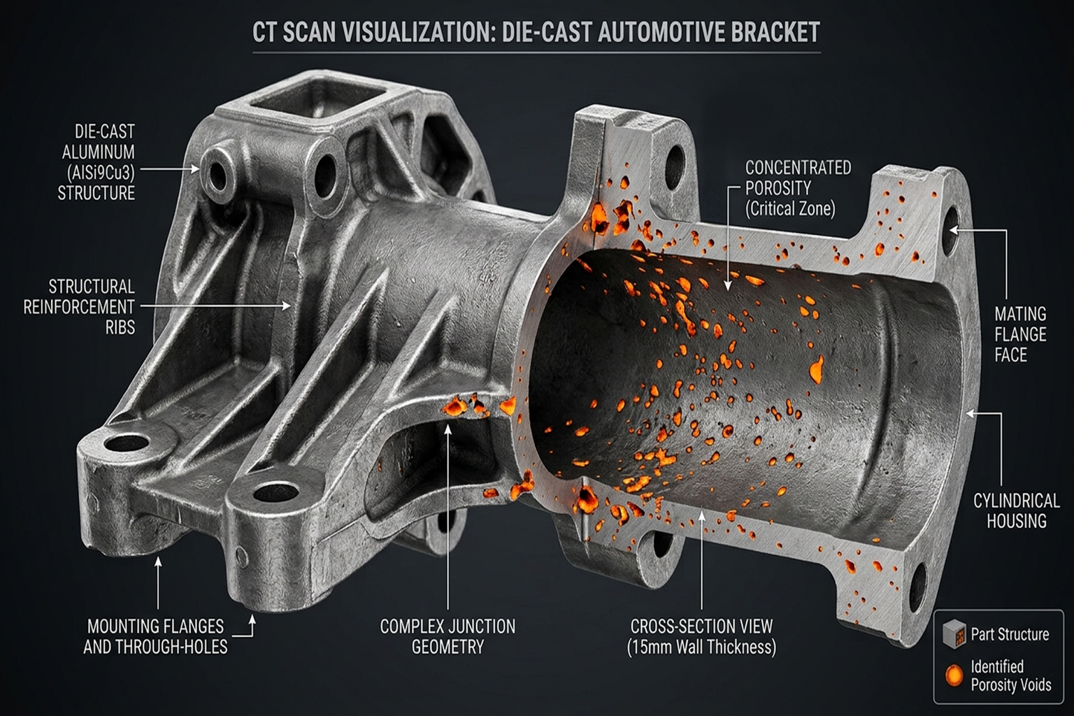
Consider a single X-ray photon emitted from the source, passing through steel, aluminum, titanium, or a multi-material assembly that requires non-destructive inspection.
Unlike light passing through glass, the photon encounters a dense field of electrons and atomic nuclei. These interactions determine the final image on the detector, which inspection engineers use to identify defects.
This distinction is critical. It determines whether an inspection reliably detects defects or fails to identify them.
Three Things That Can Happen to a Photon
When an X-ray photon enters metal, three outcomes are possible.
The photon may pass through and reach the detector, contributing to the image. It may be fully absorbed, transferring its energy to an electron and leaving the beam. Alternatively, it may be scattered, reaching the detector from an incorrect direction and adding noise instead of useful information.
The dominant outcome depends on the photon’s energy and the material’s density and atomic number. The photoelectric effect and Compton scattering are the primary processes involved, and their balance determines the clarity and reliability of the X-ray image.
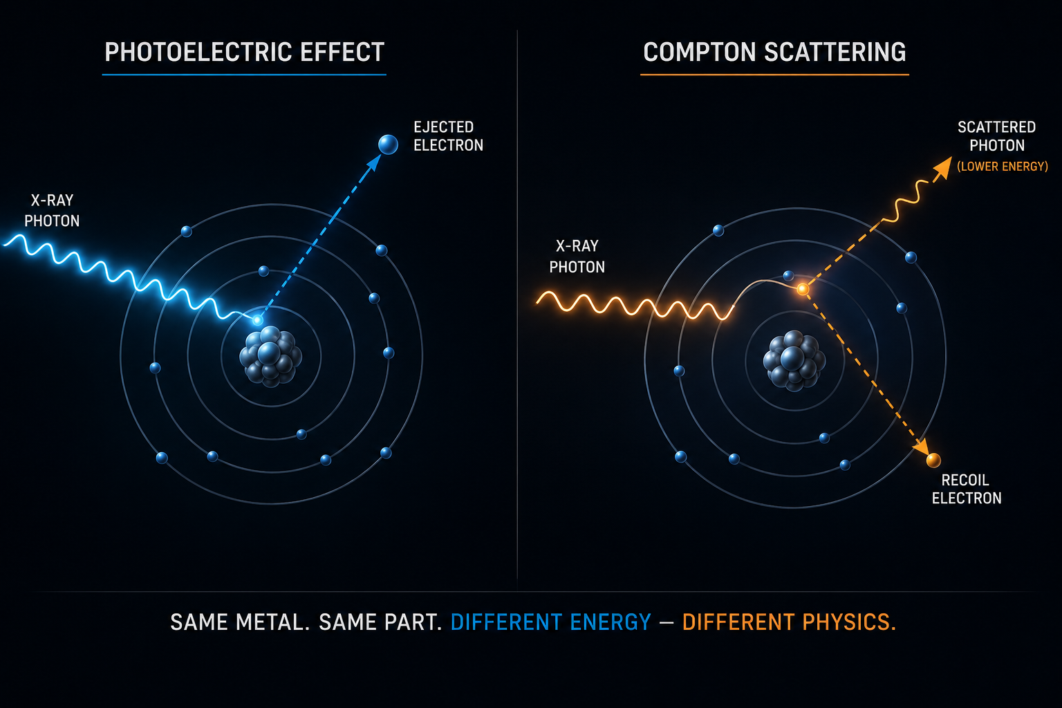
Photoelectric Effect vs. Compton Scattering
Photoelectric Effect vs. Compton Scattering
At lower X-ray energies, typically below 100–150 keV for common industrial metals, the photoelectric effect is predominant. The photon transfers all its energy to a tightly bound electron near the atom’s core, causing the photon to disappear and the electron to be ejected.
This absorption occurs more readily in materials with higher atomic numbers. As a result, steel absorbs low-energy X-rays more effectively than aluminum. Even at the same thickness, steel appears darker on the detector because fewer photons penetrate it under identical conditions.
This sensitivity to atomic number allows lower-energy X-rays to produce sharp, high-contrast images, making them ideal for detecting subtle density differences or small material variations. However, low-energy photons are absorbed quickly, so thick or dense sections can block the beam before it reaches the detector.
Compton Scattering: More Penetration, More Noise
Increasing the beam energy, which is necessary for thick steel, heavy castings, or dense alloys, shifts the dominant interaction to Compton scattering. In this process, the photon is not fully absorbed but instead transfers part of its energy to a loosely bound outer electron and is deflected, continuing in a new direction.
This process reduces image quality. Scattered photons may reach the detector but do not provide accurate information about the part’s interior, instead acting as noise. Increased scatter makes it more difficult to identify genuine defects.
Unlike the photoelectric effect, Compton scattering depends primarily on density rather than atomic number. As a result, at the high energies required to penetrate thick steel, material contrast decreases because Compton interactions do not distinguish between materials as effectively as photoelectric absorption. This increases penetration but reduces the ability to differentiate materials.
Steel vs Aluminum: Two Different Problems
This is why inspecting steel and aluminum requires distinct approaches, rather than simply adjusting equipment settings.
Aluminum’s lower atomic number and density mean that, at moderate energy, the photoelectric effect remains dominant and produces strong contrast. Defects such as porosity or inclusions are clearly visible, and scatter remains manageable.
Steel presents greater challenges. Its higher atomic number absorbs low-energy photons so effectively that thick sections may block the beam entirely, resulting in no usable image. Increasing the energy improves penetration but increases Compton scattering, which lowers contrast and adds noise. Obtaining a usable image of steel requires careful management of geometry and filtering to control scatter.
A general guideline is as follows:
- Thin aluminum castings (under 25 mm): low energy, strong contrast, very sensitive to small defects.
- Medium steel weldments (25–75 mm): moderate-to-high energy; contrast requires active management; scatter filtering required.
- Heavy steel or alloy sections (75 mm+): high-energy or alternative sources are needed; scatter becomes the main obstacle; careful setup is essential to keep sensitivity acceptable.
The primary risk is not an obviously flawed image, but one that appears acceptable while actually having reduced sensitivity. Real defects may be present but remain undetected by the system. This is the most critical failure mode in high-stakes inspection work.
Beam Hardening: A Third Wrinkle
Another important effect to consider is beam hardening.
Industrial X-ray sources emit a range of energies. As this mixed beam passes through dense metal, lower-energy photons are absorbed first, resulting in a higher-energy beam at greater depths.
In CT scanning, this effect can cause the center of a thick metal object to appear less dense than it is. In standard 2D imaging, it results in reduced contrast in thicker sections compared to thinner ones, even within uniform materials. Most CT systems correct for this during reconstruction, but the correction is most effective when tailored to the specific material being scanned.
Why This Matters Beyond the Physics Classroom
These principles guide every setup decision in inspection. Energy selection determines the dominant interaction and what the image can reveal. Filtering removes low-energy photons before they reach the part, reducing surface absorption that may obscure deeper features. Narrowing the beam angle reduces scattered radiation at the detector. For CT work, energy selection must balance penetration depth with the extent of beam hardening introduced.
An engineer who understands these mechanisms can analyze unexpected results rather than simply adjusting settings until the image appears acceptable. This diagnostic ability distinguishes reliable inspections from those based on chance.
How XRAY-LAB Puts This Into Practice
XRAY-LAB’s inspection team customizes each setup based on the specific material, thickness, and defect type, rather than using a generic approach. For dense alloys such as steel, Inconel, titanium, and copper-based materials, this involves actively managing scatter through geometry, collimation, and filtering, while balancing energy selection with image contrast.
For CT scans of dense assemblies, beam hardening correction is standard practice, with parameters adjusted to the actual material composition. This is especially important for multi-material assemblies, where hardening behavior varies throughout the scan.
For more information on these principles in practice, refer to XRAY-LAB’s guide: Industrial CT Scanning: The Complete Guide to Non-Destructive Internal Inspection. For details on internal void detection, see: Porosity Analysis and Internal Void Detection Using CT Scanning.
Frequently Asked Questions
Why does steel need higher energy than aluminum?
Steel is denser and has a higher atomic number, so it blocks low-energy X-rays almost completely. Higher energy is needed to get enough photons to form a usable image, though this comes at the cost of reduced contrast.
How does scatter actually hurt image quality?
Scattered photons reach the detector without carrying real positional information. They show up as noise layered over the genuine image, making small defects harder to distinguish.
Can one system inspect both aluminum and thick steel?
Yes, if it has a wide enough energy range and the setup is properly adjusted between materials. Using steel settings on aluminum, or vice versa, typically produces poor results.
If software handles the settings, why learn physics?
Presets are a starting point, not a guarantee. When something unexpected happens, a known defect does not show up, or a new material combination behaves oddly. Understanding physics is what lets an engineer diagnose and fix it.