CT inspection of rivet joints has revolutionized the way rivet joints are inspected, especially in industries where strength and durability are crucial. Rivet jointed parts are commonly used in automobile and aircraft assembly where parts are assembled in layers and the joints cannot be directly seen using conventional techniques.
As such, joints that seem perfect externally could have hidden flaws that compromise their efficiency. This flaw is addressed through CT scanning which facilitates an accurate assessment of the joints internally without causing any damage. This process is important as part of quality assurance in the industry, which can be further explored in “The Role of Computed Tomography in Modern Manufacturing Quality Control”.
Considering that the common voxel resolution for CT scans falls in the 30 – 80 µm range, it allows one to clearly visualize deformation of the rivet, interlocking of the joint and interaction of the layers in the joint. It should also be considered that flaw detection ability for CT is up to features two to three times larger than the voxel size.
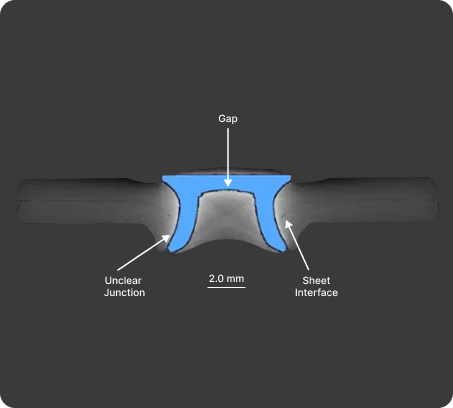
(a) CT scan highlighting internal gap, unclear junction, and sheet interface defects
Why Rivet Joints Are Critical in Manufacturing
Rivet joints are widely used because they provide strong, permanent connections, especially in lightweight and multi-material assemblies. They are particularly valuable where welding is not feasible or could damage materials. Similar inspection challenges are also seen in small precision components, as highlighted in “X-Ray Inspection for Micro-Mechanical Components: Springs, Fasteners, and Precision Parts”.
There are different rivet sizes, depending on the application; however, for common automotive and light-weight construction joints, the diameter of the rivets is normally within the range of 2 to 6 mm, and the sheet thickness is within 1 to 3 mm. The rivet forms an internal interlock during its installation that amounts up to 0.2 to 0.8 mm.
Typical applications include:
- Automotive body structures and chassis components
- Aerospace panels and lightweight assemblies
- Sheet metal fabrication and industrial equipment
In such applications, failure of one joint results in failure of other joints due to propagation of defects in the assembly.
Common Defects in Rivet Joints
Rivet joints can develop several types of internal defects during the joining process, often due to improper force, alignment, or material behavior.
These defects include:
- Incomplete interlock, reducing joint strength
- Cracks in the rivet or surrounding material
- Misalignment during installation
- Internal voids or gaps
- Excessive or uneven deformation
Why Traditional Inspection Methods Fall Short
Conventional inspection techniques have their limitations when detecting these kinds of problems internally. For one, visual inspection can only provide surface results. Destructive inspection, on the other hand, involves damaging the part by cutting it, and thus not applicable for production scenarios.
Moreover, sampling inspection poses chances of overlooking flaws during manufacture due to the high volume produced.
CT Inspection for Rivet Joints
Incorporating the use of CT scanning for defect detection in rivet joints allows engineers to gain comprehensive knowledge about the state of rivet joints, since the inner features of rivets will be observable. Engineers can thus determine the effects of the deformation of the rivet in relation to other materials, without having to make any assumptions or destroying the sample through sectional analysis. This is especially significant when dealing with multi-material assemblies wherein bonding plays a crucial role, according to “NDT for Multi-Material Assemblies: Ensuring Bonding Quality and Structural Integrity”.
The quality of the rivet depends on factors like rivet interlock size, rivet head position, and bottom thickness left behind. These characteristics are measured through sectional analysis.
It becomes especially important when applied in safety-critical applications, since the smallest of flaws can cause fatigue failure.
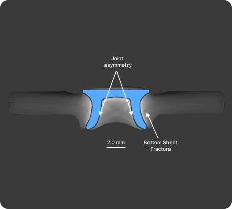
(b) CT scan of a rivet joint showing joint asymmetry and bottom sheet fracture
Key inspection capabilities include:
- Measuring interlock size and symmetry to ensure proper joint formation
- Detecting cracks and fractures that may propagate under stress
- Evaluating rivet penetration depth for process validation
- Identifying voids or internal gaps that weaken the connection
- Assessing deformation behavior across different materials
By combining visual analysis with precise measurements, CT allows manufacturers to optimize riveting parameters and ensure consistent joint quality.
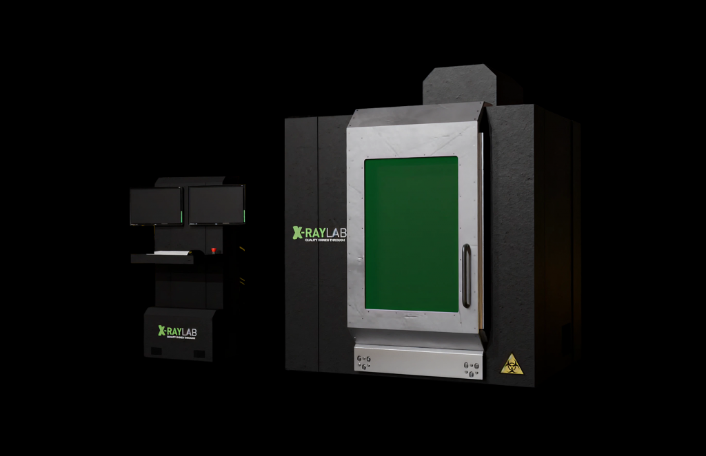
XRAY-LAB CT System for Rivet Inspection:
XRAY-LAB offers rivet analysis through high-resolution CT systems that ensure precise 3D measurement and defect detection. Our CT technology allows our engineers to identify minute differences, verify manufacturing procedures, and enhance repeatability from batch to batch.
In case of rivet connections, the CT scan usually takes place at an energy level of 160-200 kV to ensure proper scanning through several layers of material. Depending on the configuration of the scanning system and its magnification power, it is possible to obtain voxel resolution of 30-80 µm and visualize joint locking and internal clearance.
Benefits of CT for Rivet Inspection
CT scanning offers a significant advantage over traditional inspection methods by combining accuracy with efficiency.
Key benefits include:
- Non-destructive inspection of internal structures
- Full 3D visualization of complex joints
- High precision and repeatability
- Early detection of hidden defects
- Improved process optimization and quality control
These advantages make CT an essential tool for modern manufacturing environments.
Conclusion
The performance of rivet joints is essential but cannot be inspected in their internal structure through normal means. The use of industrial CT scanners presents a way out as it makes it possible for the internal structure of the component to be analyzed.
With increasing requirements in industry, CT has become a key factor in reliability and innovation.
Frequently Asked Questions
What defects can CT detect in rivet joints?
CT can identify internal cracks, voids, interlock issues, and misalignment that are not visible externally.
Is CT scanning suitable for production environments?
Yes, it can be used in both laboratory analysis and inline inspection systems.