CT artifacts or industrial CT image errors are a critical yet often underestimated challenge in industrial computed tomography. While CT scanning provides highly detailed internal visualization, the accuracy of inspection depends not only on the system’s resolution but also on how well image distortions are understood and managed.
In high-precision industries such as aerospace, electronics, and advanced manufacturing, even minor misinterpretations caused by artifacts can lead to incorrect quality decisions. This makes artifact awareness not just a technical concern, but a fundamental requirement for reliable non-destructive testing (NDT).
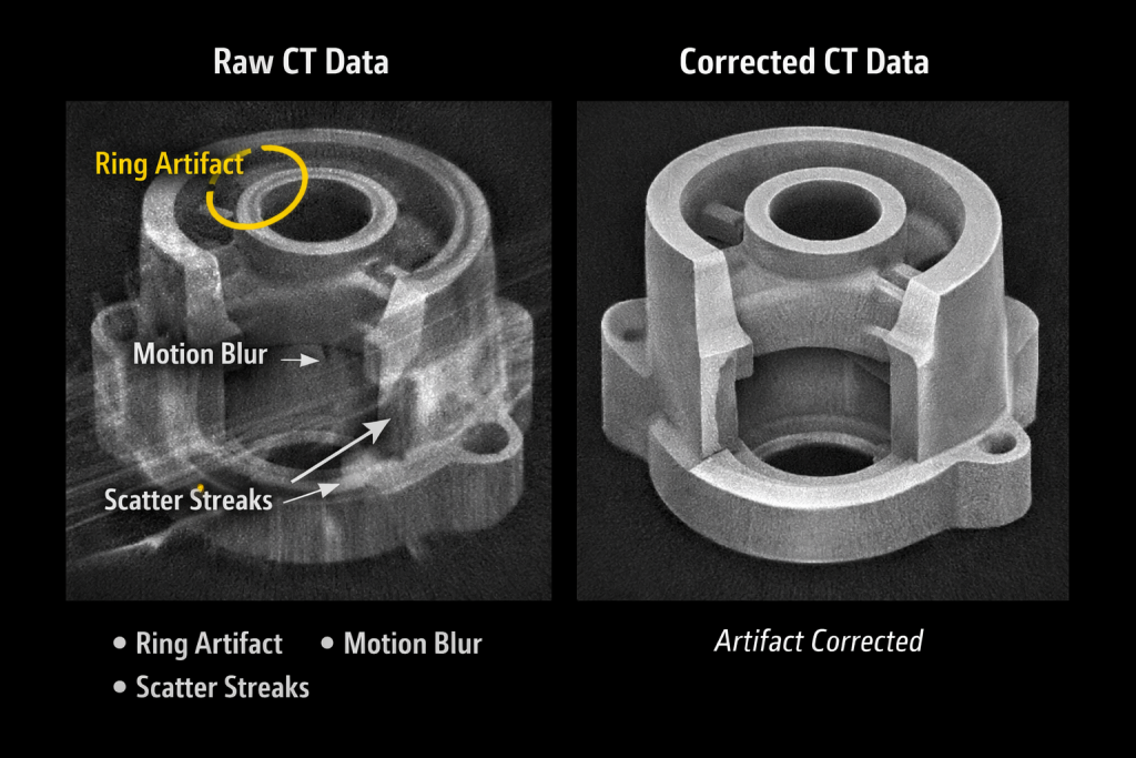
Left (Raw CT Data): Visible ring artifacts CT, streaking, or noise
Right (Corrected CT Data): Same part after CT image correction with clear geometry
What Are CT Artifacts?
CT artifacts are systematic distortions or inconsistencies in reconstructed CT images that do not correspond to the actual geometry or material composition of the inspected object. These artifacts originate from physical limitations of X-ray interaction, detector imperfections, or reconstruction algorithms.
Unlike random noise, artifacts often follow identifiable patterns, making them both detectable and, in many cases, correctable. However, if not properly recognized, they can significantly interfere with defect detection, dimensional measurement, and structural analysis.
Root Causes of CT Artifacts
To fully understand artifacts, it is important to examine their origin:
- Physics-related causes: Beam hardening, scatter radiation, and photon starvation
- System-related causes: Detector miscalibration, pixel defects, or instability
- Process-related causes: Object movement, improper scanning parameters
- Reconstruction-related causes: Algorithm limitations, data interpolation errors, and insufficient projection data leading to under sampling artifacts.
Each of these factors contributes differently depending on material type, geometry complexity, and scan configuration.
Common Types of CT Artifacts
1. Ring Artifacts: Ring artifacts appear as concentric circular patterns centered around the rotation axis. They are typically caused by inconsistencies in detector response, such as faulty or uncalibrated detector pixels.
Technical insight: Even slight variations in detector gain can propagate into full circular distortions during image reconstruction, especially in high-resolution scans.
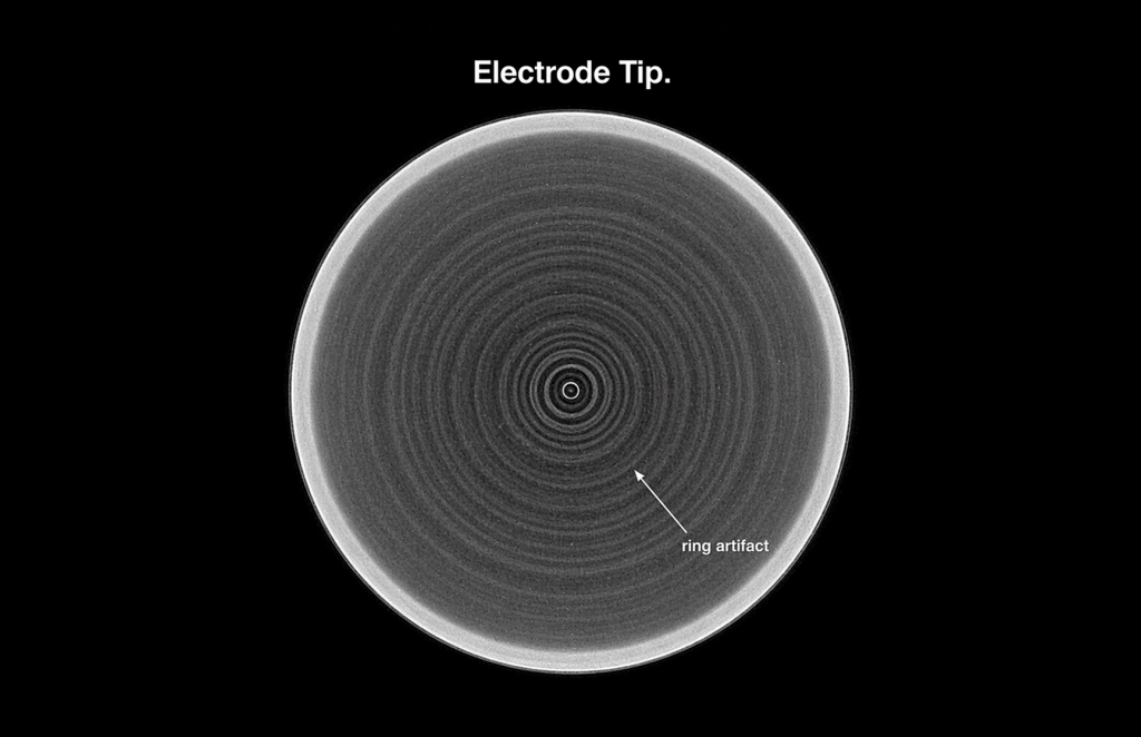
Electrode Tip Slice Showing Ring Artifact Formation
2. Motion Artifacts: Motion artifacts occur when the object shifts during the scanning process. Since CT relies on multiple projections from different angles, any movement leads to misalignment in reconstruction.
Technical insight: This results in blurred edges, ghosting effects, or duplicated structures, particularly problematic in precision metrology applications.
3. Beam Hardening Artifacts: Beam hardening is a physical phenomenon where lower-energy X-rays are absorbed more rapidly than higher-energy photons as they pass through dense materials.
Technical insight: This creates non-linear attenuation, leading to streaks, dark bands, or “cupping effects” in the reconstructed image, especially visible in metals or multi-material assemblies.
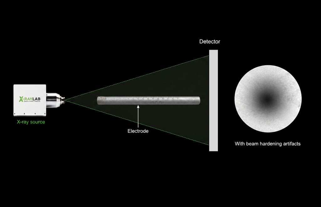
Beam Hardening Artifact in Electrode Tip
4. Scatter-Induced Artifacts (Noise & Streaking): Scattered radiation introduces unwanted signals that reduce image contrast and clarity.
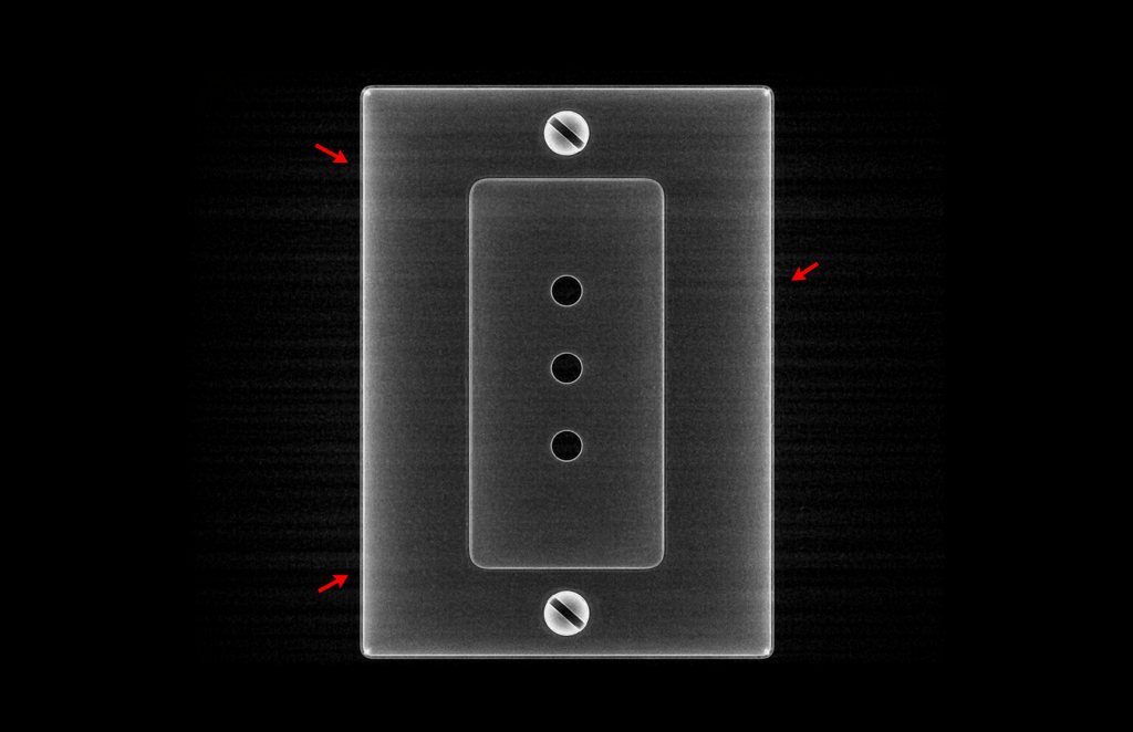
Scatter Streak Artifacts
Technical insight: In dense or complex geometries, scatter can create streak artifacts and obscure fine internal features, making micro-defect detection more challenging.
Why CT Artifacts Matter in Industrial Inspection
CT artifacts directly influence the reliability and repeatability of inspection results. In critical applications, their impact goes beyond image quality and affects engineering decisions. Artifact-induced deviations can influence dimensional measurements in the range of tens of microns, which is significant for precision engineering applications.
- False positives: Artifacts may mimic cracks, voids, or inclusions
- False negatives: Real defects may be masked by distortions
- Measurement deviations: Dimensional analysis may become inaccurate
- Reduced confidence in QA processes
For example, in EV battery inspection, a beam hardening artifact could be misinterpreted as a density variation, while in aerospace components, motion artifacts could obscure micro-cracks.
Technical Strategies for Artifact Reduction and Correction
1. System Calibration and Detector Correction: Routine calibration ensures uniform detector response and minimizes ring artifacts. Advanced systems also apply pixel-level correction algorithms in real time.
2. Optimized Scanning Parameters: Adjusting voltage (kV), current (µA), and exposure time improves signal quality and reduces beam hardening and noise. Filtration techniques can also help balance the X-ray spectrum.
Optimization of scan parameters such as tube voltage (kV), current (µA), and filtration is essential to balance penetration, contrast, and artifact reduction.
3. Mechanical Stability and Fixturing: Rigid fixturing and vibration isolation are essential to eliminate motion artifacts, particularly in high-resolution or long-duration scans.
4. Advanced Reconstruction Algorithms: Modern CT systems use iterative reconstruction and artifact correction algorithms to compensate for physical and system-induced distortions.
Examples include:
- Beam hardening correction models
- Scatter compensation techniques
- Ring artifact suppression filters
CT Artifacts vs Real Defects: How to Differentiate
Criteria | CT Artifact | Real Defect |
Pattern | Repetitive or symmetrical | Irregular and localized |
Consistency across slices | Often continuous across slices | Appears only in specific regions |
Origin | Imaging system or physics | Material or manufacturing issue |
Behavior under parameter change | May change or disappear | Remains consistent |
Artifacts are linked to the scanning process and often follow the scan pattern, while real defects stay fixed in the actual component.
Developing the ability to distinguish between the two is a key skill for inspection engineers and analysts.
Conclusion: Ensuring Accurate Inspection with Advanced CT Expertise
CT artifacts are an inherent aspect of X-ray imaging, but their impact can be effectively controlled through a combination of system optimization, process control, and expert interpretation.
In modern manufacturing environments, where precision and reliability are non-negotiable, understanding artifacts is essential for achieving accurate and repeatable inspection outcomes.
This is where XRAY-LAB adds significant value. By leveraging high-resolution CT systems, optimized scanning protocols, and advanced artifact correction techniques, Xray Lab ensures that imaging distortions are minimized and inspection data remains clear, reliable, and actionable with CT image correction. This enables manufacturers to make confident quality decisions and move closer to zero-defect production goals.
Frequently Asked Questions
What are CT artifacts?
CT artifacts are distortions in reconstructed CT images caused by physical effects, system limitations, or reconstruction errors. They do not represent actual material features but can affect defect detection, dimensional accuracy, and inspection reliability.
What is the most common CT artifact in industrial inspection?
Ring artifacts are among the most common and are usually caused by detector calibration issues.
Can CT artifacts affect dimensional measurements?
Yes, artifacts can distort geometry, leading to inaccurate measurements, especially in precision engineering applications.
How does beam hardening impact CT scans?
Beam hardening causes non-uniform attenuation, resulting in streaks or dark regions that can misrepresent material density.
Are CT artifacts more common in metal parts?
Yes, dense materials like metals are more prone to beam hardening and scatter-related artifacts.
How can engineers reduce CT artifacts during scanning?
By optimizing scan parameters, ensuring proper calibration, stabilizing the object, and using advanced reconstruction software.