Composite fuselage panels are built from dozens of stacked carbon fiber plies, bonded together under precise heat and pressure to form a structure that is both lightweight and load-bearing. Unlike metallic skin panels, where a surface crack is often visible evidence of a deeper problem, composite panels can carry serious internal defects, delamination, porosity, fiber misalignment, without any external sign at all. Non-destructive CT scanning has become the standard method for verifying what lies beneath the surface, both during manufacturing and across the panel’s service life.
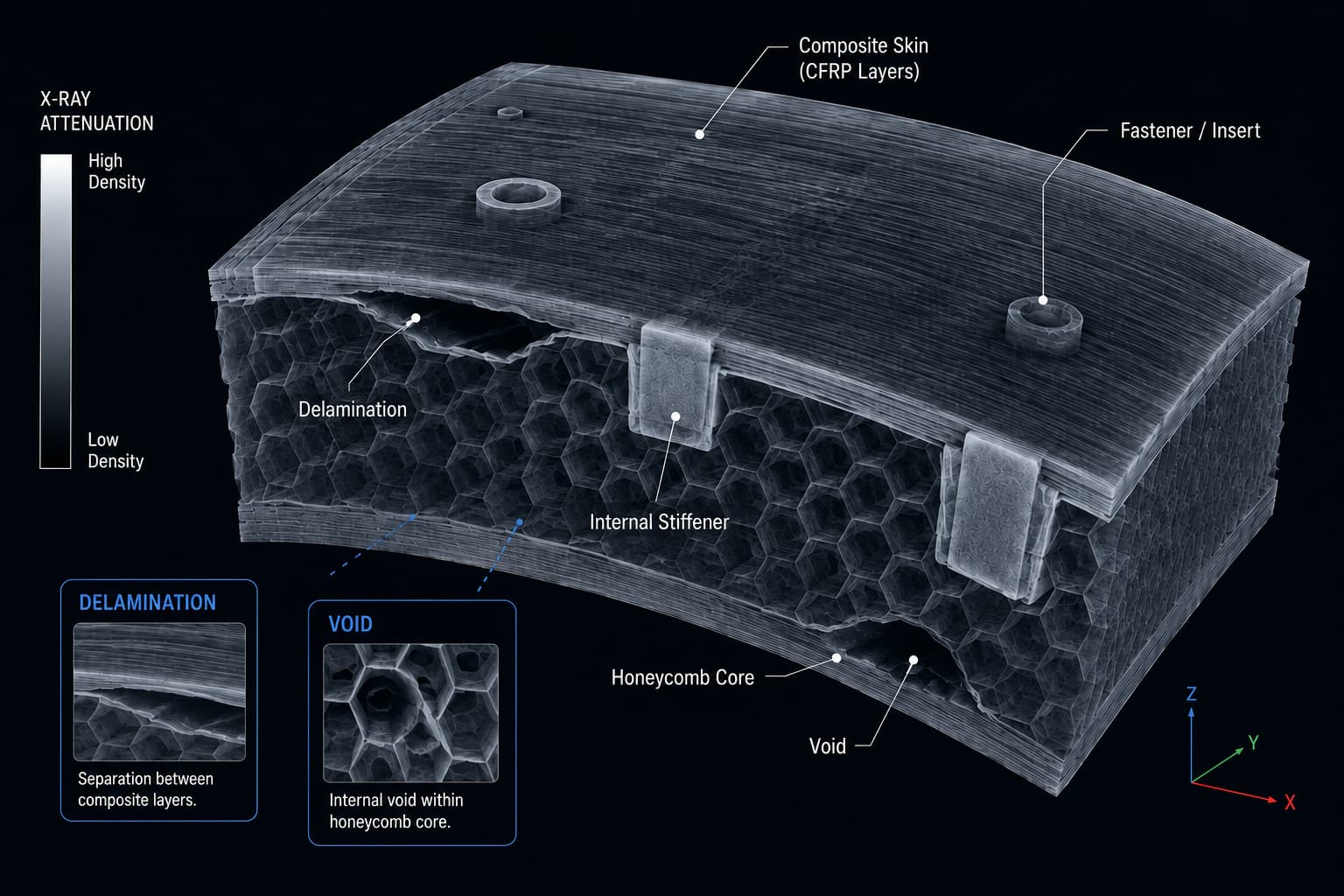
A 3D industrial CT reconstruction of a composite fuselage panel reveals its internal architecture, from CFRP layers and honeycomb core to stiffeners, fastener inserts, delamination, and internal voids.
Why Composite Fuselage Panels Require Non-Destructive CT Scanning
A fuselage panel’s structural performance depends entirely on the integrity of its internal ply structure. If layers separate, resin does not fully cure, or fibers shift out of alignment during layup, the panel can lose a significant portion of its designed strength while still looking flawless from the outside. Because composite panels cannot be sectioned or cut open for inspection without destroying the part, and because surface-level techniques like visual inspection or tap testing only reach near-surface defects, CT scanning is one of the few methods capable of resolving the full ply stack in three dimensions without damaging the panel.
Common Defects Found in Aerospace Composite Inspection
Aerospace composite inspection typically focuses on a recurring set of defect types, each with different structural consequences:
- Delamination — separation between adjacent plies, often caused by impact, thermal stress, or manufacturing inconsistency
- Porosity — trapped air or volatile gas pockets formed during cure, which reduce interlaminar strength
- Fiber wrinkling or misalignment — plies that shift out of their intended orientation during layup, altering load paths
- Resin-rich or resin-starved zones — uneven resin distribution that weakens bonding between layers
- Foreign object inclusions — debris or backing material trapped between plies during fabrication
- Disbonds at stiffener or stringer interfaces — loss of adhesion where internal structural elements are bonded to the panel skin
Each of these defect types has a distinct density or geometric signature under CT, which is what allows them to be distinguished from one another in a single scan rather than requiring separate inspection methods.
How CT Delamination Detection Works in Layered Composite Panels
Delamination detection is one of the most common reasons composite fuselage panels are scanned. Because CT reconstructs the panel as a volumetric dataset, it can be sliced parallel to the ply stack, perpendicular to it, or at any custom angle, which makes it possible to trace a delamination plane across its full extent rather than seeing only a cross-sectional snapshot. This is particularly important for delaminations that form at an angle to the panel surface, where a single 2D X-ray projection would compress the defect and understate its true size. Volumetric CT data instead allows the defect to be measured in three dimensions, giving engineers a defensible basis for accept or reject decisions against structural repair manuals.
Porosity and Fiber Wrinkling in Composite Fuselage CT Inspection
Manufacturing-stage defects tend to be more subtle than in-service damage, and porosity is the clearest example. Individual voids may be smaller than a millimeter, but when distributed across a ply interface they lower the panel’s interlaminar shear strength in ways that are difficult to detect with ultrasonic methods alone. CT scanning resolves both the size and spatial distribution of porosity, which matters because scattered microporosity and a single larger void of the same total volume can have very different effects on structural performance. Fiber wrinkling, meanwhile, shows up in CT as a local deviation in ply geometry rather than a density change, and volumetric imaging is often the only non-destructive method able to confirm it against the intended layup design.
Detecting Impact Damage That Aerospace Composite Inspection Must Catch
Composite panels are particularly vulnerable to a phenomenon known in the industry as barely visible impact damage, where an impact from a tool drop, hail, or ground handling equipment leaves little or no visible surface mark while creating substantial internal delamination and fiber breakage beneath. This mismatch between surface appearance and internal condition is one of the strongest arguments for CT-based aircraft structural testing during scheduled maintenance, since a panel that passes visual inspection can still be carrying damage that meaningfully reduces its residual strength.
Aircraft Structural Testing Applications Across the Lifecycle
CT inspection of composite fuselage panels supports several distinct stages of an aircraft program:
- Manufacturing quality control-verifying ply count, layup accuracy, and cure quality before a panel is approved for assembly
- First article and design verification-onfirming that a new panel design matches its engineering intent across the full structure, not just sampled locations
- In-service damage assessment-quantifying delamination or impact damage found during scheduled maintenance to support repair or replacement decisions
- Repair verification-confirming that a bonded or scarf repair has fully re-established structural continuity with the surrounding panel
- Root-cause failure analysis-investigating field returns or test failures to determine whether a defect originated during manufacturing or in service
This inspection scope builds on the same volumetric imaging principles XRAY-LAB applies in its broader work on detecting hidden defects in composite materials, and shares much of its defect vocabulary, delamination, porosity, fiber misalignment, with XRAY-LAB’s experience inspecting other large-scale composite structures such as CFRP wind turbine blades.
XRAY-LAB's Capability for Composite Fuselage CT Inspection
XRAY-LAB supports aerospace manufacturers and MRO providers with high-resolution CT scanning suited to large composite structures, combining volumetric defect detection with precise dimensional verification against CAD or repair manual tolerances. Scan parameters, voltage, filtering, and voxel resolution, are adjusted to the panel’s thickness and ply density so that delamination planes, porosity, and fiber-level detail remain resolvable in the same dataset. This capability extends beyond fuselage skin panels to other composite and bonded aerospace structures, including the fastener and joint inspection work covered in XRAY-LAB’s article on CT inspection of aerospace fasteners, giving manufacturers a consistent, non-destructive inspection approach across an aircraft’s composite structure.
Frequently Asked Questions
Can CT scanning detect delamination that is not visible on the panel surface?
Yes. CT reconstructs the full ply stack in three dimensions, which is what allows it to detect delamination and impact damage that produces no visible surface mark, commonly referred to as barely visible impact damage.
How does CT distinguish porosity from delamination in a composite panel?
The two defect types have different geometric signatures in the reconstructed volume. Porosity appears as small, distributed voids within a ply or resin layer, while delamination appears as a planar separation running along a ply interface.
Is CT scanning suitable for large fuselage panel sections, or only small samples?
CT scanning is used across both scales, from coupon-level material qualification to full structural panel sections, with scan parameters adjusted for the size and material density of the part being inspected.
For manufacturers and MRO providers evaluating a composite panel’s structural condition, XRAY-LAB’s CT inspection team can advise on scan setup and defect reporting suited to specific panel geometries and repair manual requirements.