Retrofitting X-ray inspection systems into existing production environments inevitably introduces geometric, mechanical, and temporal constraints. These constraints do not merely affect system layout; they directly determine which defects remain detectable and which become invisible. In retrofit scenarios, inspection performance is defined less by hardware capability and more by inspection strategy.
Xray-Lab specializes in retrofit-aware inspection planning, ensuring that defect detectability remains controlled, measurable, and application-specific despite physical limitations.
Table of Contents
Retrofit Constraints as a Defect Detectability Problem
Retrofit installations impose fixed inspection angles, limited tube–detector distances, constrained part orientations, and reduced inspection time per component. Each constraint selectively reduces sensitivity to certain defect types, particularly orientation-dependent cracks, low-density voids, and interface-related discontinuities.
Xray-Lab approaches retrofit projects by first defining which defects must be detected, rather than adapting inspection parameters blindly to the available space.
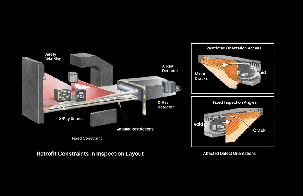
A schematic inspection layout highlights typical retrofit constraints, including fixed beam paths and restricted angular access. Overlay diagrams show which defect orientations are affected under these conditions.
Xray-Lab Retrofit-Aware Inspection Planning
Xray-Lab’s retrofit-aware inspection planning begins with defect-driven system configuration. Instead of relying on generic inspection settings, scan parameters are optimized specifically for the constrained geometry of the retrofitted system.
This includes targeted tube voltage and filtration selection to maximize contrast within shortened penetration paths, optimized detector positioning to enhance sensitivity in critical regions, and inspection angle selection aligned with known defect orientations in the product group.
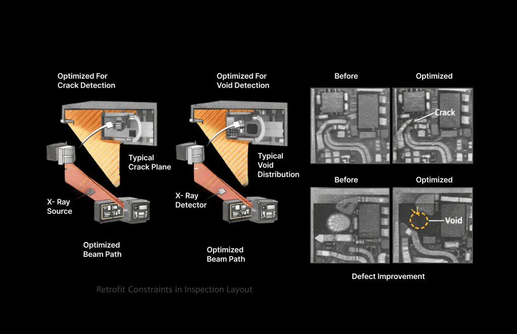
Annotated inspection geometry diagrams show optimized beam alignment relative to typical crack planes and void distributions. Comparative images demonstrate contrast improvement achieved through parameter optimization under retrofit conditions.
Visualizing Inspection Coverage Before and After Retrofit
Understanding inspection coverage is essential in retrofit environments. Xray-Lab provides explicit visualization of inspection coverage zones to prevent false assumptions about defect detectability.
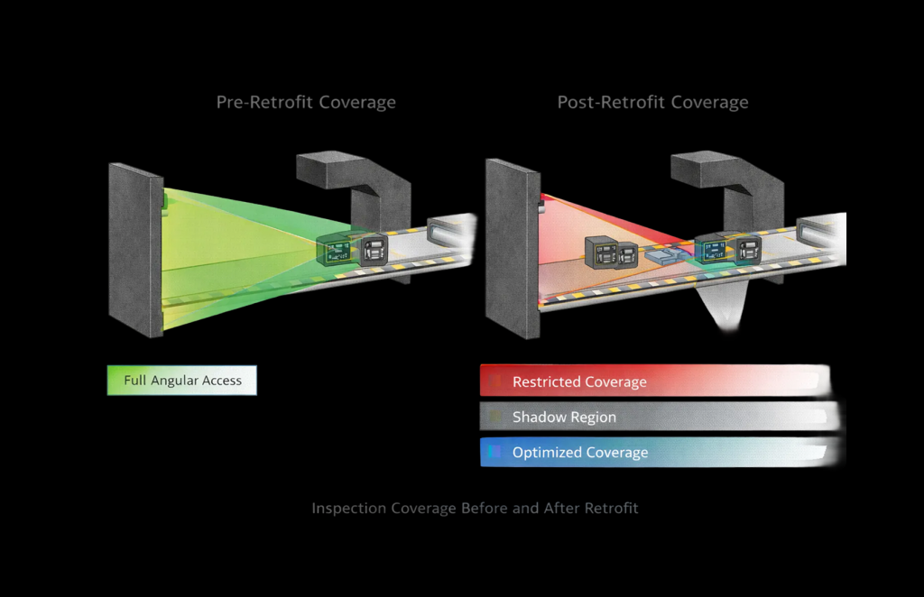
Pre-retrofit coverage diagrams show idealized inspection envelopes with full angular access. Post-retrofit diagrams illustrate real inspection coverage, highlighting restricted zones and newly introduced shadow regions. Color-coded overlays indicate where Xray-Lab’s optimized strategies recover defect visibility despite geometric limitations.
Managing Retrofit-Induced Blind Zones with Targeted Solutions
Blind zones are not treated as unavoidable compromises but as controlled risk areas. Xray-Lab evaluates whether blind zones intersect with load-bearing regions, bonding interfaces, or known failure origins.
When necessary, Xray-Lab implements targeted mitigation strategies such as dual-orientation inspection, localized parameter shifts for specific product zones, or selective offline CT validation for high-risk features.
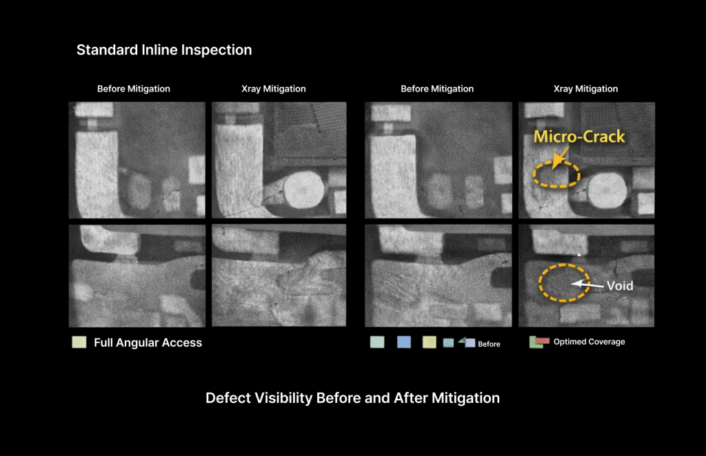
CT slices reveal defects missed under standard inline conditions but detected using Xray-Lab’s adjusted inspection strategy. Side-by-side comparisons demonstrate defect visibility before and after mitigation.
Product-Group-Specific Added Value
Different product groups respond differently to retrofit constraints. Xray-Lab tailors inspection strategies accordingly.
For electronic assemblies, internal solder joint wetting and micro-void clusters are visualized despite fixed orientations. For polymer components, density gradients and compression damage are detected through optimized contrast settings. For battery and multi-material assemblies, interface integrity and alignment defects are revealed using defect-oriented scan planning.
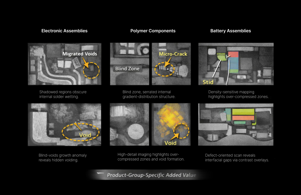
Product-group CT examples show common retrofit-sensitive defects with annotations explaining why standard retrofit inspection would miss them and how Xray-Lab’s approach recovers visibility.
Why Xray-Lab’s Approach Increases Inspection Reliability
Retrofitted X-ray systems often appear operational while silently losing sensitivity to critical defect types. Xray-Lab eliminates this risk by making defect detectability explicit, visual, and application-driven.
The added value lies not in installing hardware, but in ensuring that inspection results remain technically meaningful under real production constraints.
Conclusion
Retrofit constraints fundamentally shape what an X-ray inspection system can detect. Without defect-oriented planning, these constraints can undermine inspection reliability. Xray-Lab’s retrofit-aware inspection methodology ensures that defect detectability remains the defining performance metric, delivering reliable inspection outcomes even in highly constrained retrofit environments.
Frequently Asked Questions
How does Xray-Lab determine which defects are critical in retrofit scenarios?
Xray-Lab evaluates defect criticality based on product function, load paths, and known failure mechanisms specific to the application.
Can inspection coverage really be improved without mechanical changes?
Yes. In many cases, optimized scan parameters and orientation strategies significantly enhance defect visibility even within fixed geometries.
When is offline CT used in retrofit projects?
Offline CT is used selectively when inline retrofit constraints limit visibility in safety- or load-critical regions.
Does Xray-Lab support retrofit planning before installation?
Yes. Xray-Lab offers retrofit feasibility analysis and, for selected components, a free initial sample analysis.
